background image

NI PXIe-4844 Installation Guide and Specifications

4

ni.com

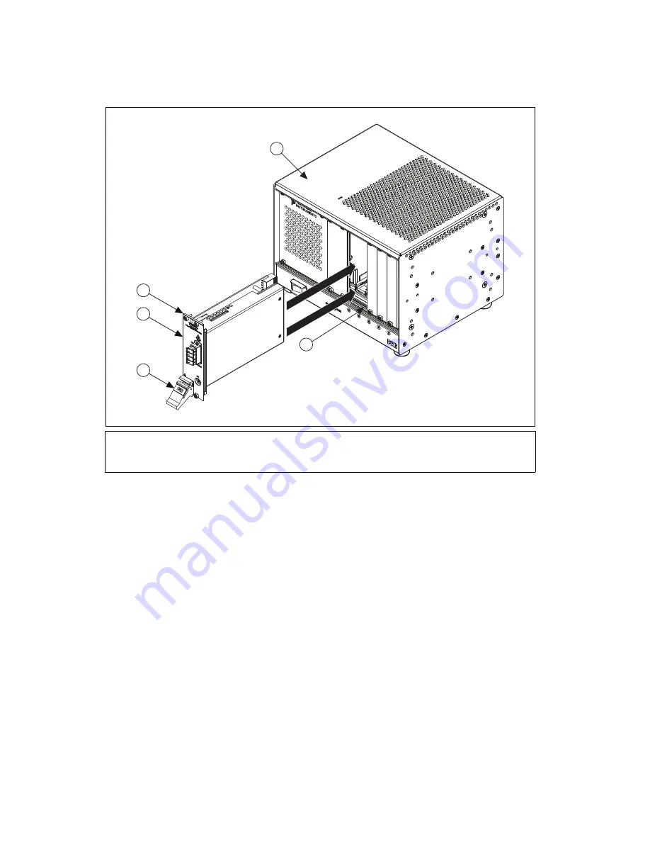
Figure 2.  

Sliding the NI PXIe-4844 into the Chassis

10. Raise the injector/ejector handle to latch the module into the chassis. The front panel of the 

NI PXIe-4844 should be even with the front panel of the chassis.

11. Tighten the four front panel mounting screws to 0.31 N · m (2.7 lb · in.) on the top and bottom of 

the module front panel to secure the NI PXIe-4844 to the chassis.

12. Power on the chassis.

Removing the NI PXIe-4844 from the PXIe Chassis

To remove the NI PXIe-4844 from the PXI Express chassis, complete the following steps:

1.

Power off the chassis.

2.

Remove any cables or sensors attached to the NI PXIe-4844. 

3.

Loosen the four front panel mounting screws on the module.

4.

Press the injector/ejector handle down.

5.

Slide the module out of the chassis.

6.

Place the NI PXIe-4844 in its original antistatic bag. Store the module within its hard-shelled 
plastic case.

1

NI PXI Express Chassis

2

Injector/Ejector Rail

3

Injector/Ejector Handle

4

NI PXIe-4844

5

Front Panel Mounting Screw (4x)

1

2

5

4

3

NI PXIe-1

073

Summary of Contents for PXIe-4844

Page 1: ...isible to the human eye but it can seriously damage your eyesight Caution Do not modify the NI PXIe 4844 module This may result in hazardous radiation exposure from the laser source Electromagnetic Compatibility Guidelines This product was tested and complies with the regulatory requirements and limits for electromagnetic compatibility EMC as stated in the product specifications These requirements...

Page 2: ...e module in the original antistatic package and hard shelled plastic case What You Need to Get Started LabVIEW 2009 or later PXI Express chassis with controller or MXI Express card or built in FBG sensors Multiplexer for additional channels optional Installing the NI OSI Driver Software Install the NI OSI driver software on the host computer before installing the NI PXIe 4844 module Refer to readm...

Page 3: ...the slot number PXI Express Hybrid Peripheral Slot a PXI Express hybrid slot marked with the letter H and a solid circle containing the slot number PXI Express System Timing Slot a PXI Express timing slot marked with a square surrounding a solid circle containing the slot number 7 Remove the filler panels covering the selected slots 8 Align the NI PXIe 4844 with the card guides on the top and bott...

Page 4: ...12 Power on the chassis Removing the NI PXIe 4844 from the PXIe Chassis To remove the NI PXIe 4844 from the PXI Express chassis complete the following steps 1 Power off the chassis 2 Remove any cables or sensors attached to the NI PXIe 4844 3 Loosen the four front panel mounting screws on the module 4 Press the injector ejector handle down 5 Slide the module out of the chassis 6 Place the NI PXIe ...

Page 5: ...eak and damage the module Connect the LC APC connector on the sensor to an available LC APC connector port on the module Figure 3 NI PXIe 4844 Channels and AUX Port Caution When connecting any accessory to the AUX port install a ferrite bead NI part number 781233 01 on the connecting cable as close to the AUX port as possible You can order ferrite beads directly from NI by part number by visiting ...

Page 6: ... measurements remain within specifications over the life of the product Using the NI OSI Explorer and LabVIEW VIs The NI OSI driver software installs the NI OSI Explorer and the NI OSI LabVIEW VIs Use the NI OSI Explorer to identify and configure the optical sensors connected to the NI PXIe 4844 Use the Optical Measurement VIs in LabVIEW to perform optical sensing measurements To get started 1 Sel...

Page 7: ... The left most slot must be a PXI Express PXI Express Hybrid or PXI Express System Timing slot Slot compatibility x4 x8 and x16 PXI Express or PXI Express Hybrid slots Safety Standards This product meets the requirements of the following standards of safety for electrical equipment for measurement control and laboratory use IEC 61010 1 EN 61010 1 UL 61010 1 CSA 61010 1 Note For UL and other safety...

Page 8: ...ch by module number or product line and click the appropriate link in the Certification column Shock and Vibration Mechanical shock Operating IEC 60068 2 7 Annex A section A 4 Table A 1 15 g peak half sine 11 ms pulse Non operating IEC 60068 2 7 25 g peak half sine 11 ms pulse Random vibration Operating ETSI 300 019 2 3 0 15 grms 5 to 100 Hz Non operating IEC 60068 2 64 0 8 grms 10 to 150 Hz Envir...

Page 9: ...t ni com environment weee Where to Go for Support The National Instruments Web site is your complete resource for technical support At ni com support you have access to everything from troubleshooting and application development self help resources to email and phone assistance from NI Application Engineers National Instruments corporate headquarters is located at 11500 North Mopac Expressway Aust...

Page 10: ...ir respective companies For patents covering National Instruments products technology refer to the appropriate location Help Patents in your software the patents txt file on your media or the National Instruments Patent Notice at ni com patents Refer to the Export Compliance Information at ni com legal export compliance for the National Instruments global trade compliance policy and how to obtain ...

Reviews: