background image

If the installation window does not appear, navigate to the drive, double-click it, and
double-click 

autorun.exe

.

3.

Follow the instructions in the installation prompts.

Note


Windows users may see access and security messages during

installation. Accept the prompts to complete the installation.

4.

When the installer completes, select 

Restart

 in the dialog box that prompts you to restart,

shut down, or restart later.

Installing the PXI-5154

Caution


To prevent damage to the PXI-5154 caused by ESD or contamination,

handle the module using the edges or the metal bracket.

1.

Ensure the AC power source is connected to the chassis before installing the module.

The AC power cord grounds the chassis and protects it from electrical damage while you
install the module.

2.

Power off the chassis.

3.

Inspect the slot pins on the chassis backplane for any bends or damage prior to
installation. Do not install a module if the backplane is damaged.

4.

Remove the black plastic covers from all the captive screws on the module front panel.

5.

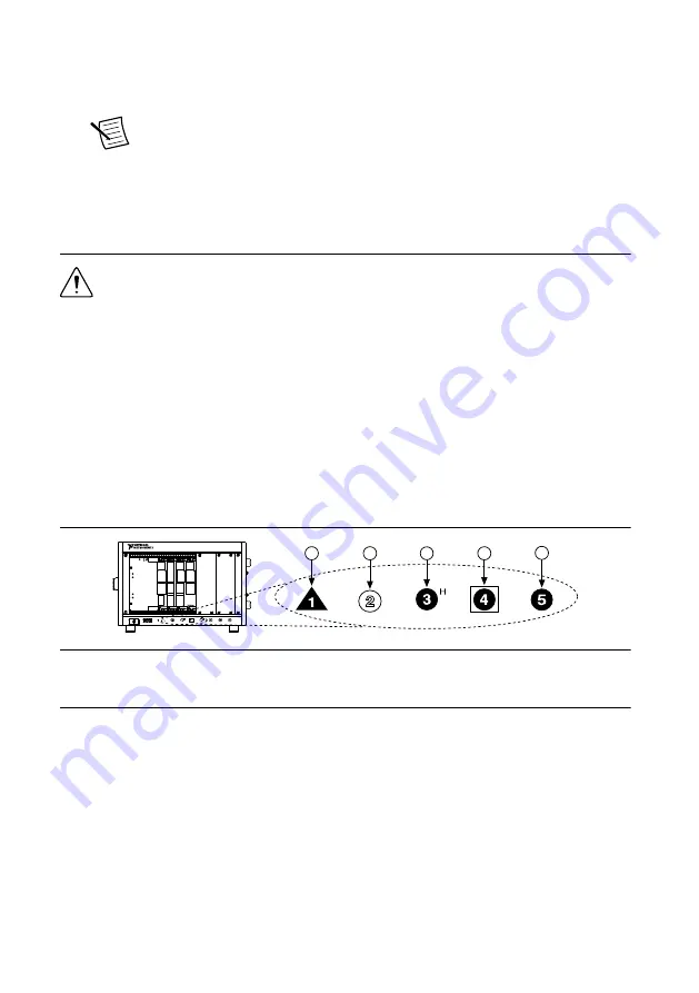
Identify a supported slot in the chassis. The following figure shows the symbols that
indicate the slot types.

Figure 2. Chassis Compatibility Symbols

NI PXIe-1062Q

1

2

3

4

5

1. PXI Express System Controller Slot
2. PXI Peripheral Slot
3. PXI Express Hybrid Peripheral Slot

4. PXI Express System Timing Slot
5. PXI Express Peripheral Slot

PXI-5154 modules can be placed in PXI peripheral slots or PXI Express Hybrid
peripheral slots.

6.

Touch any metal part of the chassis to discharge static electricity.

7.

Ensure that the ejector handle is in the downward (unlatched) position.

8.

Place the module edges into the module guides at the top and bottom of the chassis. Slide
the module into the slot until it is fully inserted.

PXI/PCI-5154 Getting Started Guide

  | 

© National Instruments

  | 

5

Summary of Contents for PCI-5154

Page 1: ...manner not described in this document Contents Electromagnetic Compatibility Guidelines 2 Verifying the System Requirements 2 Unpacking the Kit 2 Kit Contents 3 Other Equipment 3 Preparing the Environ...

Page 2: ...ion Furthermore any changes or modifications to the product not expressly approved by National Instruments could void your authority to operate it under your local regulatory rules Verifying the Syste...

Page 3: ...l items not included in your kit to install or operate your device PXI Devices A PXI chassis a PXI SCXI combination chassis or a PXI CompactPCI chassis with a controller and the chassis documentation...

Page 4: ...068 2 1 and IEC 60068 2 2 Relative humidity range 10 to 90 noncondensing Tested in accordance with IEC 60068 2 56 Maximum altitude 2 000 m at 25 C ambient temperature Pollution Degree 2 Indoor use onl...

Page 5: ...slot pins on the chassis backplane for any bends or damage prior to installation Do not install a module if the backplane is damaged 4 Remove the black plastic covers from all the captive screws on th...

Page 6: ...imize cooling air flow depending on your application 12 Power on the chassis Note For more information about maximizing cooling air flow refer to the Maintain Forced Air Cooling Note to Users included...

Page 7: ...anufacturers use a securing lever made of plastic to secure PCI devices such a lever is unacceptable and must be removed Use the screw provided in the kit to screw down the device Otherwise you must u...

Page 8: ...CH 0 CH 1 TRIG PFI 1 PFI 0 ACCESS ACTIVE CH0 CH1 TRIG PFI0 PFI1 Table 1 PXI PCI 5154 Front Panel Signal Connections Connector Description Function CH 0 CH 1 Standard BNC female connector Analog input...

Page 9: ...PE 1 Launch MAX 2 In the configuration tree expand Devices and Interfaces to see the list of installed NI hardware Installed modules appear under the name of their associated chassis 3 Expand your Cha...

Page 10: ...libration capabilities which you can access programmatically with NI SCOPE and your ADE or interactively with NI SCOPE SFP or MAX Related Information Making a Measurement on page 12 What Should I Do i...

Page 11: ...Microsoft Visual C C Use examples located in the file directory Users Public Documents National Instruments NI SCOPE examples You can modify an NI SCOPE C example to create an application with Micros...

Page 12: ...he acquisition display 5 If the SFP is not already running click Run Making a Measurement with LabVIEW 1 Launch LabVIEW 2 Select Help Find Examples 3 Open the example VI that you want to use by select...

Page 13: ...to NI RTSI Cable and select the device you want to add For more information about connecting PCI devices refer to NI High Speed Digitizers Help Programming Reference NI TClk Synchronization Help Troub...

Page 14: ...e Device Manager Operating System Description Windows 10 8 1 Right click the Start button and select Device Manager Windows 7 Select Start Control Panel Device Manager 5 If you are using a PXI or PXI...

Page 15: ...Where to Go Next NI PXIe 4112 EXPLORE LEARN CREATE DISCOVER Located online at ni com manuals the application development environment ADE for your application about hardware features or review device...

Page 16: ...hone support outside the United States visit the Worldwide Offices section of ni com niglobal to access the branch office websites which provide up to date contact information support phone numbers em...

Reviews: