STJ / MPX-32D
Quick Start Guide
Version 2.01
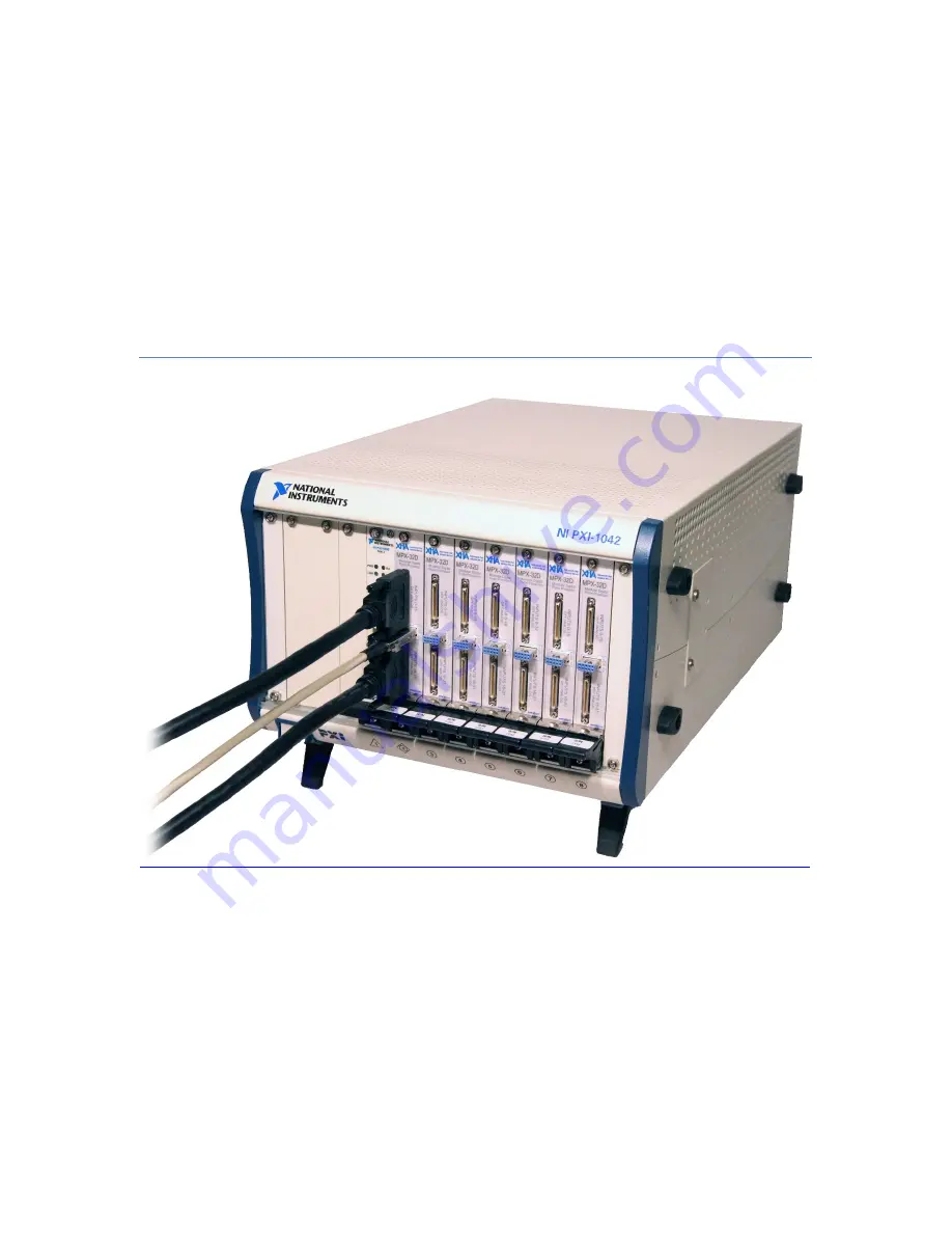
This document describes XIA’s instrumentation system for setting up an STJ system with one or more
MPX-32D 32-channel modular digital processors.
Page 1: ...STJ MPX 32D Quick Start Guide Version 2 01 This document describes XIA s instrumentation system for setting up an STJ system with one or more MPX 32D 32 channel modular digital processors ...
Page 2: ...uts and Outputs 8 STJ Input Connector HDDSUB 78 Pinout 8 Quick Start Guide 9 STJ or Diagnostic Pulser Input 9 System Setup 9 Software Installation 9 STJ Preamplifier Installation 9 PXI Crate Installation 9 Review PCI BUS Connections 10 EDIT the Configuration INI File 10 Firmware FDD Files and Decimation 10 Start ProSPect 10 Using the ProSpect Software 11 Overview of Typical Usage 11 Channel Select...
Page 3: ...cay Time 18 Adjust the ADC Offset 20 MCA Panel 20 Preset Run Constraint 21 Statistics 21 Region of Interest ROI and Calibration 22 GainMatch Panel 22 Mapping Panel List Mode Data Acquisition 23 List Mode Variant 23 Mapping Options 24 Acquiring List Mode Data 25 Save the INI FIle 26 ...
Page 4: ...log 32 channel preamplifier module s o STJ I O module which includes an STJ input override switch Linear voltage supply module that provides power to the custom crate Associated interconnecting cables MPX 32D DIGITIZER MODULE XIA s MPX 32D is a 32 channel digitizer and modular pulse processor that resides in a computer controlled PXI crate Its primary function is to measure pulse heights i e event...
Page 5: ...al gain passes through a software controlled octal variable gain amplifier VGA stage The VGA is controlled at the Bank level by the DSP parameters BANK0ADCGAIN BANK1ADCGAIN BANK2ADCGAIN and BANK3ADCGAIN The digitized signal can be approximately expressed in units of ADC least signficant bits LSB as ADC LSB 10 BANKnADCGAIN 5 20 input signal mV For example with BANK0ADCGAIN 20 a 100 mV signal on cha...
Page 6: ...ule is a 32 channel preamplifier card with an associated software controlled STJ bias voltage DAC and input connection relay for each channel A backplane diagnostic pulser signal is routed to each channel via a separate relay Fig 2 STJ Analog 32 channel preamplifier card ...
Page 7: ...3 STJ Analog front end schematic INPUTS OUTPUTS AND CONTROLS Name Connector Type Description Analog Outputs 0 15 SAMTEC VRDPC 50 01 M RA 16 differential pair preamplifier outputs Analog Outputs 16 31 SAMTEC VRDPC 50 01 M RA 16 differential pair preamplifier outputs LVDS I O Harting 27 21 121 8006 1 diff pair analog input is received as a pulser input 3 LVDS digital inputs used for communications a...
Page 8: ...s well as the user pulser analog input and a diagnostic channel 0 output for each STJ Analog module installed INPUTS OUTPUTS AND CONTROLS Name Connector Type Description Kill switch Toggle switch Left hand position overrides software control of STJ input relays STJs are disconnected Right hand position software controls STJ input relays Channel 0 Outputs SMA x4 A single ended version of the channe...
Page 9: ...n the same order Note that XIA does not provide HDDSUB 78 cables to connect the custom crate to the STJ detectors in the cryostat The cable should be shielded and as short as possible Custom Backplane Eurocard x5 4 backplane connectors each carry the STJ input signals from one HDDSUB 78 connector power supply connections and the pulser input to an STJ Analog module A fifth slot left most is reserv...
Page 10: ...e the two from other ground connections Ideally the two pieces of hardware are physically co located and bolted together If that s not possible a thick copper braid may be sufficient Signal integrity issues almost always trace back to poor grounding between the custom crate and the detector cryostat or improper STJ wiring within the cryostat itself The custom crate can safely be powered on off and...
Page 11: ...ci_slot values as necessary and save the INI file Save the INI file frequently as settings are adjusted and note that you can also save and retrieve to from different INI files You can also use the Generate Configuration File dialog accessible under the Tools menu to generate a new INI file and view compatible XIA modules detected on the PXI bus FIRMWARE FDD FILES AND DECIMATION XIA provides three...
Page 12: ...preamplifiers and then wait for preamplifiers to settle as indicated by the green LED on the custom crate 2 Start ProSpect or initialize the system by selecting your modified INI file 3 Optionally verify the STJ biasing by running a BiasScan operation and inspecting Fiske Mode locations vs bias voltage settings for all channels 4 Optionally verify the presence of input pulses and the Decay Time se...
Page 13: ...or the System tab in this application is the enabling and disabling of channels performed by clicking in the Disable column adjacent to each channel When a channel is disabled data acquisition will be disabled for that channel which reduces communications and processing overhead Channels that aren t wired to actual STJ pixels for example can and should be disabled The channel enable disable settin...
Page 14: ...m closing when in the left hand position Make sure this switch is in the right hand position Click the STJ Relay Enable Disable button so that it changes from green to red Note that the LED on the analog chassis corresponding to the selected STJ Analog module will change from solid green to solid red when the relays are closed PULSER The Pulser Settings control a rudimentary built in pulser circui...
Page 15: ...as voltage the Preamplifier Polarity setting should be negative and vice versa When the polarity is set correctly ADC pulses should be positive as viewed in the Scope panel DECAY TIME When using STJ detectors the preamplifier Decay Time can only be determined after the STJ bias voltage has been set and x rays are present In our experience the Decay Time ranges from a few 10 s to 100 s of microseco...
Page 16: ...n section above THRESHOLD The STJ processing pipeline includes two separate digital filters Trigger fast and Energy slow The trigger filter output is optimized for speed and is used exclusively to detect input pulses and pileup The slow energy filter is optimized for noise reduction It is used primarily for energy measurement but can also be used to detect very small pulses i e low energy events b...
Page 17: ...re FDD Files and Decimation section We recommend always using the Peak Sensing Capture Method This means that the largest energy value within an appropriate window is recorded which always yields the optimum energy resolution With the Peak Sampling method you will need to adjust the Peak Sampling Time to achieve optimal energy resolution We recommend setting the Fast Trigger Filter Peaking Time to...
Page 18: ...or the run to complete The run time depends primarily on the number of Scan Points and the Wait Time By default the green bias current plot is selected Click and drag in the plot to quickly zoom Click and drag on any of the axes to quickly pan Right click and select Full Scale to zoom all the way out To zoom in on the red noise plot first right click and select Zoom Reference then click and drag a...
Page 19: ...acquisition occurs simultaneously for all channels in the currently selected modules We strongly recommend reviewing this section before trying to acquire MCA or list mode Mapping data Set the Trace Type to ADC Set the Trigger Type to Threshold Turn on the x ray source or alternatively enable the pulser in the Auxiliary tab Press the Get Trace button to simultaneously acquire a plot of the ADC for...
Page 20: ...orrectly As a check change the Trace Type to Scaled Energy and acquire more traces The output of the energy filter should be a trapezoid with slightly curved edges If there is significant over damping or under shoot after the pulse the Decay Time is set too low If there is significant under damping or over shoot after the pulse the Decay Time is set too high ...
Page 21: ...oltages have been adjusted The offset value with a range of 1 8191 corresponds directly to the 12 bit ADC and should be set as low as possible but high enough that the ADC waveform NEVER drops below 0 due to noise We typically set the offset to 128 which is roughly 3 above the ADC minimum and which makes 97 of the ADC range available for pulses The special value 0 resets the DAC to mid range MCA P...
Page 22: ...nds automatically To apply a Preset Run constraint select the desired constraint from the drop down combo box and enter the desired value in the adjacent field before starting the run Fig 11 The MCA histogram and statistics are shown for a 10 second Fixed Real Time Preset Run with the built in pulser with default settings used as the input source with the recommended Preamp Gain 150 mV keV and Dyn...
Page 23: ...e selected channel The peak should jump to the desired energy when new data is acquired Fig 12 Here is a similar MCA histogram to the one displayed in Fig 11 but this time the peak has been calibrated to 1 keV and the STJ Relay has been enabled i e WITHOUT additional noise from the dummy detector circuit Note that now the Mean is 999 98 eV and the FWHM is 2 86 eV GAINMATCH PANEL The GainMatch tool...
Page 24: ...EL LIST MODE DATA ACQUISITION The Mapping panel is used for list mode acquisition e g each event generates an event record with channel ID time stamp and energy value Event records during a run are saved to a binary file Please refer to the STJ List Mode Specification for further details on the different list mode options and the event record buffer header and binary file formatting Some of the la...
Page 25: ...nstraint defines the run duration The run terminates when the total number of events on all channels in the system equals this value If the Indefinite Run box is checked the Total Number of Pixels constraint is ignored instead the run proceeds until the user presses the Stop Mapping button The Mapping Pixels Per Buffer constraint limits the number of events stored in the SRAM ping pong buffers in ...
Page 26: ...DATA We recommend first acquiring data with the Save Data box unchecked to test that data is actually acquired as indicated by the n buffers pacifier below the Mapping Options section of the panel which increments every time a ping pong buffer is read The refresh rate is 65536 number of channels count rate seconds For example with 32 channels at 1 kcps the refresh rate is approximately 2 seconds I...
Page 27: ...to overwrite the current INI file Remember that certain settings e g LISTMODEVAR and GATEWAIT must be edited manually in the INI file Typically these are entered just above the END 0 line in the default definitions section These manual edits will be preserved during Save Configuration and Save Configuration As operations however they must be re entered if the Generate Configuration tool is used to...