background image

©

 National Instruments Corporation

5

Getting Started with the NI PCIe-1429 and NI PCIe-1430
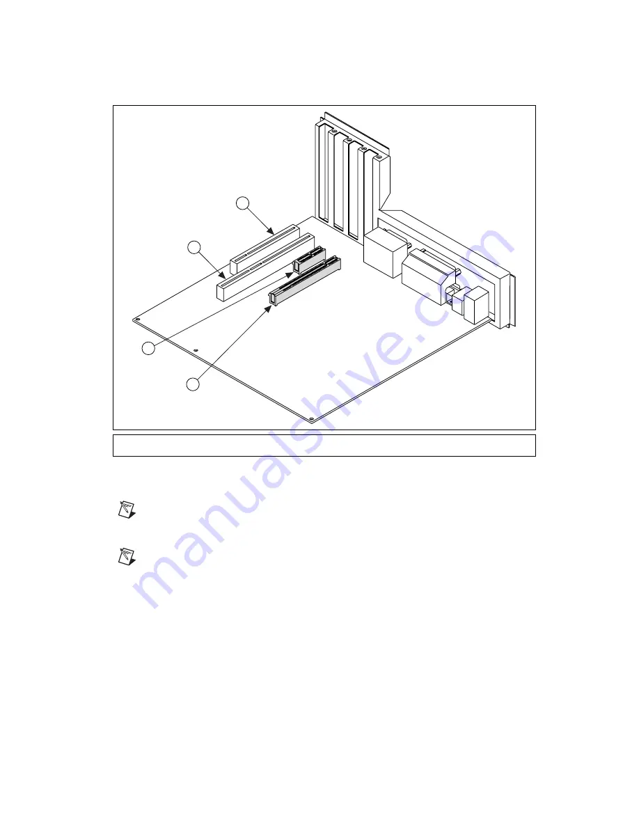
Figure 1.  

PC Expansion Slots

6.

Remove your device from the antistatic package and gently rock the device into the slot. The 
connection may be tight, but do 

not

 force the device into place.

Note

Check that the bracket of your device aligns up with the hole in the back panel rail of the 

computer chassis.

7.

Secure the device mounting bracket to the back panel rail of the computer.

Note

If you will be using the NI Camera Link I/O Extension Board, refer to the 

NI Camera Link I/O 

Extension Board User Guide 

for installation instructions.

8.

Replace the computer cover.

9.

Connect the MDR 26-pin Camera Link cable to the Camera Link-compatible camera. Refer to
your camera manufacturer documentation for specific instructions about how to connect the cable 
to your camera.

10. Connect the Camera Link cable to the Camera Link connector on the NI 1429 or NI 1430 front 

panel.

11. Plug in and power on the computer.

1

PCI 32-bit Connector 

2

PCI 64-bit and/or PCI-X Connector

3

PCIe x4 Connector 

4

PCIe x16 Connector

4

2

1

3

Summary of Contents for NI PCIe-1429

Page 1: ...29 Camera Link compatible camera One MDR 26 pin Camera Link cable for Base configuration cameras Two MDR 26 pin Camera Link cables of the same length for Medium or Full configuration cameras NI 1430 U...

Page 2: ...you must follow when installing and operating the device Do not operate the device in a manner not specified in the documentation Misuse of the device may result in a hazard and may compromise the sa...

Page 3: ...asurement Category I is for measurements performed on circuits not directly connected to the electrical distribution system referred to as MAINS4 voltage This category is for measurements of voltages...

Page 4: ...rotect yourself and the computer from electrical hazards the computer must remain unplugged until the installation is complete 3 Remove the computer cover to expose the expansion slots Caution Install...

Page 5: ...il of the computer Note If you will be using the NI Camera Link I O Extension Board refer to the NI Camera Link I O Extension Board User Guide for installation instructions 8 Replace the computer cove...

Page 6: ...the NI 1429 and NI 1430 to acquire images from a specific camera Without this camera file the driver does not have the information necessary to configure the NI 1429 and NI 1430 to recognize the image...

Page 7: ...xternal Connections Number of external trigger I O lines 1 Note External TTL lines on the 15 pin D SUB connector become unavailable when the trigger source is set as an optically isolated input or an...

Page 8: ...1 UL 61010 1 CSA 61010 1 Note For UL and other safety considerations refer to the product label or visit ni com certification search by model number or product line and click the appropriate link in t...

Page 9: ...ction for electronic compatibility EMC and product safety You can obtain the DoC for your product by visiting ni com certification If your product supports calibration you can obtain the calibration c...

Page 10: ...l Instruments trademarks Other product and company names mentioned herein are trademarks or trade names of their respective companies For patents covering National Instruments products refer to the ap...

Reviews: