


©
National Instruments Corporation
11
MID-7654/7652 Servo Power Motor Drive User Guide
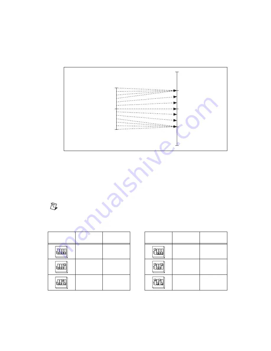
Figure 5 shows the command voltage input to current output relationship for periods of time greater than
2.7 seconds. The maximum current output corresponds to the continuous current limit,
I
cont
. Therefore,
command voltages that would result in a higher current output than
I
cont
when the gain is applied instead
result in a current output of
I
cont
.
Figure 5.
Input Voltage to Output Current Relationship for Periods of Time Greater Than 2.7 Seconds
The amplifier peak and continuous current limits have been factory set for 5 A continuous current output
and 10 A peak current output. Verify that these settings are appropriate for your application before
powering your motors.
Use DIP switches 1 through 4 on each of the 9-position DIP switch banks to set the continuous current
limit for each axis. Use DIP switches 5 through 8 on each of the 9-position DIP switch banks to set the
peak current limit for each axis. Refer to Figures 1 and 3 for the location of the continuous current limit
and peak current limit switches. Table 5 shows the DIP switch settings for all possible current limit
settings.
Note
The switches shown in Table 5 show the settings for switches 1 through 4, which are the
continuous current DIP switches. Configure the settings for switches 5 through 8 in the same manner
to set the peak current values.
Table 5.
Continuous and Peak Output Current DIP Switch Settings
Switch
Continuous
Current (A)
Peak
Current (A)
Switch
Continuous
Current (A)
Peak
Current (A)
5.00
10.00
1.25
2.50
4.50
9.00
1.15
2.30
3.80
7.55
1.10
2.20
0 A
Input Command Voltage
0 V
+I
pe
a
k
+I
cont
–I
pe
a
k
–I
cont
Output Current
G
a
in Applied
+V
m
a
x
–V
m
a
x
1
O
N
2 3 4
1
O
N
2 3 4
1
O
N
2 3 4
1
O
N
2 3 4
1
O
N
2 3 4
1
O
N
2 3 4