Chapter 2
Configuration and Installation
2-6
ni.com
VIDEO0 Input Mode
VIDEO0 has two different input sources via a BNC connector or a 68-pin
VHDCI port and two different input modes—referenced single-ended
(RSE) and differential (DIFF) input. When you use the BNC input for
VIDEO0, set the input mode to RSE (W1 populated). When you use
the 68-pin VHDCI port for VIDEO0, set the input mode for either RSE
or DIFF.
When in RSE mode, the video input uses one analog input line, which
connects to the video multiplexer circuitry. The negative input to the video
multiplexer is tied internally to analog ground. When in DIFF mode, the
video input uses two analog input signals. One signal connects to the
positive input of the video multiplexer circuitry while the other input
signal connects to the negative input of the video multiplexer circuitry.
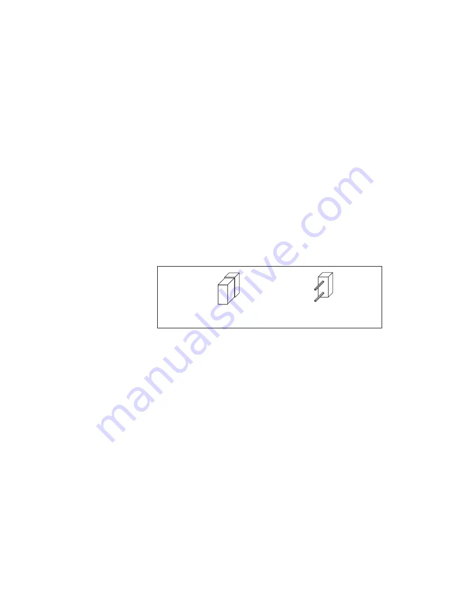
Jumper W1 controls the input mode selection, as shown in Figure 2-3.
Unpopulating W1 configures VIDEO0 for DIFF mode. Populating W1
configures VIDEO0 for RSE mode.
Figure 2-3.
Configuring VIDEO0 with Jumper W1
Video channels 1, 2, and 3 are always in differential mode. To take an RSE
measurement on these channels, tie the negative terminal of the connector
to ground (Pins 26 or 60 on the 68-pin VHDCI connector). See Chapter 4,
, for more information on pin assignments.
a. RSE Mode (Default)
b. DIFF Mode


