Appendix D
Operation of the SCSI
© National Instruments Corp.
D-7
GPIB-SCSI-A User Manual
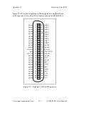
Figure D-1 shows the arrangement of these signals on a standard 50-pin
SCSI connector. This is the SCSI connector used on the GPIB-SCSI-A.
1
2
3
4
5
6
7
8
9
10
11
12
13
14
15
16
17
18
19
20
21
22
23
24
25
26
27
28
29
30
31
32
33
34
35
36
37
38
39
40
41
42
43
44
45
46
47
48
49
50
reserved
ground
ground
ground
ground
ground
ground
open
ground
ground
ground
ground
ground
ground
ground
ground
ground
ground
ground
ground
ground
ground
ground
ground
reserved
ground
ground
ground
I/O*
SDB0*
SDB1*
SDB2*
SDB3*
SDB4*
SDB5*
SDB6*
SDB7*
SDBP*
ground
reserved
TERMPWR
reserved
ATN*
BSY*
ACK*
RST*
MSG*
SEL*
C/D*
REQ*
Figure D-1. Standard 50-Pin SCSI Connector

