Chapter 3
Analog Output Timing/Control
DAQ-STC Technical Reference Manual
3-124
©
National Instruments Corporation
•
Generates the DAC address up to 16 DAC channels
•
Generates the AOFFRT signal
•
Generates the AOFREQ signal
The bitfield AO_UPDATE_Output_Select controls the output UPDATE. The output can be
one of high impedance, ground, output enabled, or output enabled and inverted. When
enabled, the signal pulses to update the DAC.
The bitfield AO_UPDATE2_Output_Select controls the output UPDATE2. The output can be
one of high impedance, ground, output enabled, or output enabled and inverted. When
enabled, the signal also pulses to update the DAC.
3.8.7 Nominal Signal Pulsewidths
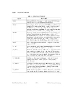
Table 3-9 lists the nominal pulsewidths for the signals associated with analog input. Notice
that only the UPDATE and UPDATE2 signals can use either the source or output clocks; all
of the others must use the indicated clock source. These are only the nominal pulsewidths; the
actual synchronization edges and propagation delays are detailed in section
.
Table 3-9.
Analog Output Nominal Signal Widths
Signal
Source Clock
Output Clock
UPDATE
1
1, 3
UPDATE2
1
1, 3
LDAC0
1
1, 3
LDAC1
1
1, 3
TMRDACWR
—
2, 3
CPUDACWR
—
2, 3
TMRDACREQ
Asserted when data needed, removed at TMRDACWR.
AO_ADDR<0..3>
Changes on trailing edge of TMRDACWR. Bus address pass
through during CPUDACWR.
CHRDY_OUT
From CPUDACREQ to edge of CPUDACWR.
DACWR0
—
2, 3
DACWR1
—
2, 3
AOFFRT
—
1


