background image

Unpacking the Kit

Notice


To prevent electrostatic discharge (ESD) from damaging the device, ground

yourself using a grounding strap or by holding a grounded object, such as your
computer chassis.

1.

Touch the antistatic package to a metal part of the computer chassis.

2.

Remove the device from the package and inspect the device for loose components or any
other sign of damage.

Notice


Never touch the exposed pins of connectors.

Note


Do not install a device if it appears damaged in any way.

3.

Unpack any other items and documentation from the kit.

Store the device in the antistatic package when the device is not in use.

What You Need to Get Started

Kit Contents

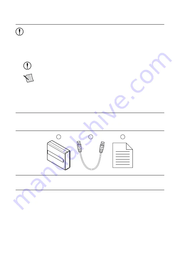
Verify that the following items are included in the cRIO-9805 kit.

1

3

2

1. cRIO-9805
2. Ethernet cable
3. Safety, Environmental, and Regulatory Information document

Required Components

CompactRIO controller or host computer

Power supply, 9 V to 30 V, 5 W maximum

Recommended Components

Internet access

Additional, required-length Ethernet cable(s), user provided

cRIO-9805 Getting Started Guide

  | 

© National Instruments

  | 

3

Summary of Contents for cRIO-9805

Page 1: ...the module to power connecting to Ethernet and configuring the device and the network Figure 1 cRIO 9805 Front Panel 3 5 2 1 4 cRIO 9805 SYNC 0 1 3 2 RESET POWER STATUS V C INPUT 5 W MAX 9 to 30 V 1...

Page 2: ...et Signal Gigabit Ethernet Signal Pin Pinout TX TX_A 1 1 2 3 4 5 6 7 8 TX TX_A 2 RX RX_B 3 No Connect TX_C 4 No Connect TX_C 5 RX RX_B 6 No Connect RX_D 7 No Connect RX_D 8 Table 4 Ethernet LED Indica...

Page 3: ...t install a device if it appears damaged in any way 3 Unpack any other items and documentation from the kit Store the device in the antistatic package when the device is not in use What You Need to Ge...

Page 4: ...tRIO systems contact NI Grounding the cRIO 9805 For information about grounding the cRIO 9805 refer to the Expansion Module for CompactRIO User Manual on ni com manuals Connecting the cRIO 9805 Connec...

Page 5: ...nnecting the cRIO 9805 to the Controller Power Connector The cRIO 9805 requires a 9 V to 30 V power supply You can power both the module and a CompactRIO or CompactDAQ controller from the same power s...

Page 6: ...tRIO controller 6 Tighten the power connector screw flanges to 0 20 N m to 0 25 N m 1 8 lb in to 2 2 lb in of torque 7 Connect a ferrule to the other end of the power wires 8 Push the ferruled wires d...

Page 7: ...ing kit What to Do Complete the following steps to connect the cRIO 9805 to a network Figure 4 Connecting the cRIO 9805 to a Controller cR IO 904 cR IO 9805 0 1 2 3 Figure 5 Connecting the cRIO 9805 t...

Page 8: ...Can be a Windows computer or a real time controller with the NI Linux Real Time operating system such as the IC 317x cRIO 9035 9039 Sync cRIO 904x cRIO 905x or cDAQ 913x for LabVIEW Real Time Node Ca...

Page 9: ...troubleshooting Ideal for low number of nodes NI recommends a maximum of 15 nodes per chain No additional switch needed Can cover long distances Disadvantages Any unpowered nodes and or node failure...

Page 10: ...ffic patterns can make troubleshooting difficult Only allows one chain per switch Requires more switches to configure larger systems More Options Note For more information about designing Ethernet mea...

Page 11: ...1 The LED lights both blue and yellow to indicate the module is resetting 2 The LED lights solid yellow to indicate the module is booting 3 The LED lights solid blue to indicate the module is powered...

Page 12: ...At ni com support you have access to everything from troubleshooting and application development self help resources to email and phone assistance from NI Application Engineers Visit ni com services f...

Page 13: ...ments EULAs and third party legal notices in the readme file for your NI product Refer to the Export Compliance Information at ni com legal export compliance for the NI global trade compliance policy...

Reviews: