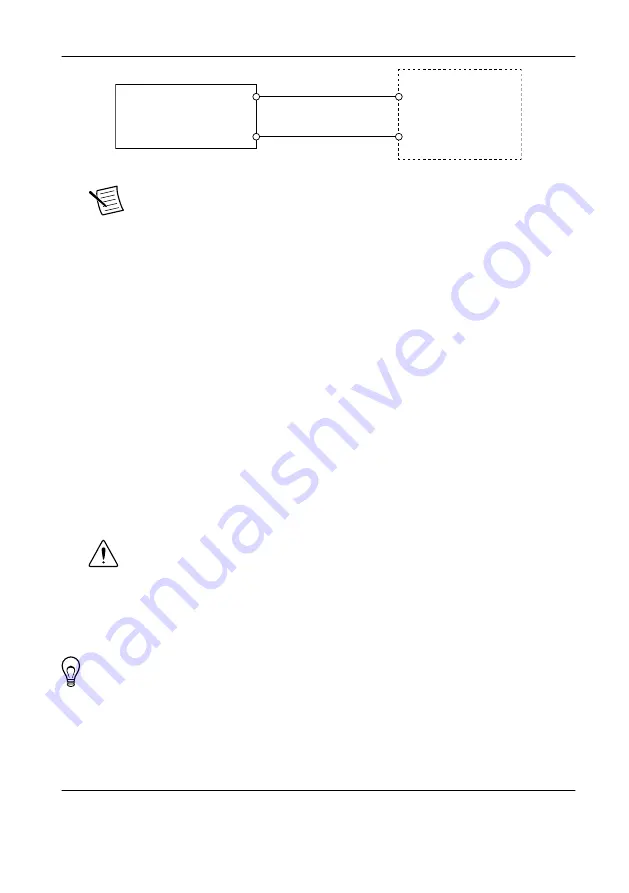
background image

Figure 3.

 cRIO-9064 Power Connections

Power Connector

C

V

Power Supply

+

Note


The C terminals are internally connected to each other.

4.

Tighten the terminal screws on the power connector to 0.20 N · m to 0.25 N · m
(1.8 lb · in. to 2.2 lb · in.) of torque.

5.

Install the power connector on the front panel of the cRIO-9064.

6.

Tighten the power connector screw flanges to 0.20 N · m to 0.25 N · m (1.8 lb · in. to
2.2 lb · in.) of torque.

7.

Power on the power supply.

Powering On the cRIO-9064

When you power on the cRIO-9064 for the first time, the device boots into safe mode. The
POWER LED illuminates, the STATUS LED illuminates briefly, and then the STATUS LED
blinks twice every few seconds.

Connecting the cRIO-9064 to the Host Computer

Complete the following steps to connect the cRIO-9064 to the host computer using the USB
device port.
1.

Power on the host computer.

2.

Connect the cRIO-9064 to the host computer using the USB A-to-B cable.

Caution


NI requires the use of a locking USB cable (157788-01) to meet the 

shock and vibration specifications. Refer to the specifications on 

ni.com/

manuals

 for shock and vibration specifications.

The device driver software automatically detects the cRIO-9064. If the device driver
software does not detect the cRIO-9064, verify that you installed the appropriate NI
software in the correct order on the host computer.

Tip


You can also use the Ethernet port to connect directly to the host computer or

network. Refer to the user manual on 

ni.com/manuals

 for more information about

Ethernet connections.

Configuring the System in Measurement &
Automation Explorer (MAX)

Complete the following steps to find the system in MAX.

8

  | 

ni.com

  | 

NI cRIO-9064 Getting Started Guide

Summary of Contents for cRIO-9064

Page 1: ...afety protection built into the product if the product is damaged in any way If the product is damaged return it to NI for repair Safety Guidelines for Hazardous Locations The cRIO 9064 is suitable fo...

Page 2: ...own to be nonhazardous Table 1 Hazardous Location Retention Accessories Port Required Accessory Part Number USB Device Port NI Locking USB Cable 157788 01 USB Host Port NI Industrial USB Extender Cabl...

Page 3: ...authority to operate it under your local regulatory rules Caution To ensure the specified EMC performance operate this product only with shielded cables and accessories Special Conditions for Marine...

Page 4: ...nectors Note Do not install a device if it appears damaged in any way 3 Unpack any other items and documentation from the kit Store the device in the antistatic package when the device is not in use V...

Page 5: ...on the C Series module 3 Align the C Series module with a slot and seat it in the slot until the latches lock in place Removing C Series Modules Verify that power is not connected to the I O connecto...

Page 6: ...Use Ring lug Wire 2 1 mm2 14 AWG or larger Screwdriver Phillips 2 What to Do Complete the following steps to ground the cRIO 9064 1 Attach the ring lug to the wire 2 Remove the grounding screw from th...

Page 7: ...s the POWER LED indicators Table 2 POWER LED Indicators LED Color LED Pattern Indication Green Solid The cRIO 9064 is powered on and the connected power supply is adequate Off The cRIO 9064 is powered...

Page 8: ...eps to connect the cRIO 9064 to the host computer using the USB device port 1 Power on the host computer 2 Connect the cRIO 9064 to the host computer using the USB A to B cable Caution NI requires the...

Page 9: ...ring prompts you to do so 2 Enter a unique name for your system in the Hostname field 3 Click the Security Configuration icon 4 Click Login 5 In the Login dialog box enter the username admin and leave...

Page 10: ...rmat of 172 22 11 x 2 In MAX expand your system under Remote Systems 3 Select the Network Settings tab to configure the IP and other network settings 4 Optional Use the RJ 45 Ethernet port 1 to reconn...

Page 11: ...ul and appropriate for your application skip to Step 6 4 In MAX expand your system under Remote Systems 5 Select the Network Settings tab to configure the IP and other network settings 6 Reboot the cR...

Page 12: ...are has been improperly installed on the cRIO 9064 An error can occur when an attempt to upgrade the software is interrupted Reinstall software on the cRIO 9064 Refer to the Measurement Automation Exp...

Page 13: ...actriodevguide Software Support ni com info swsupport Support ni com support SOFTWARE CompactRIO Sample Projects LabVIEW Create Project HARDWARE NI cRIO 9064 Specifications ni com manuals NI cRIO 9064...

Page 14: ...nch office websites which provide up to date contact information support phone numbers email addresses and current events Refer to the NI Trademarks and Logo Guidelines at ni com trademarks for inform...

Reviews: