1-16
|
ni.com
Chapter 1
Getting Started with the cDAQ Controller
Caution
Your installation must meet the following requirements for space and
cabling clearance, as shown in Figure 1-10:
•
Allow 50.8 mm (2 in.) on the top and the bottom of the controller for air
circulation.
•
Allow 50.8 mm (2 in.) in front of modules for cabling clearance for common
connectors, such as the 10-terminal, detachable screw terminal connector.
Using the cDAQ Controller on a Desktop
Complete the following steps to install the NI desktop mount kit, part number 781988-01, on the
cDAQ controller.
9.
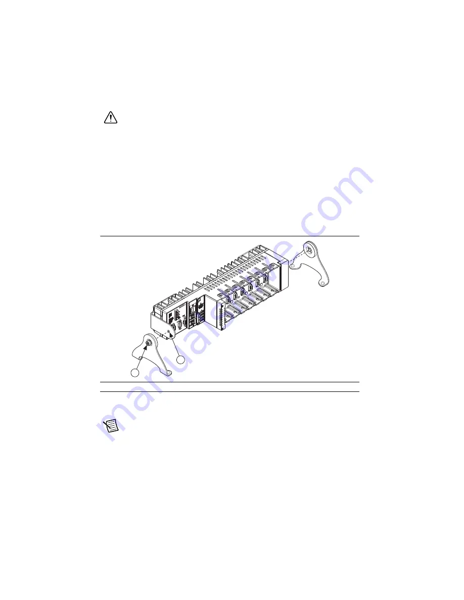
Align one of the end brackets with the mounting hole at one of the ends of the controller,
as shown in Figure 1-11.
Figure 1-11.
Connecting the End Brackets to the Controller
10. Use a number 2 Phillips screwdriver to tighten the captive screw on the end bracket.
11. Repeat steps 9 and 10 to attach the other end bracket to the other end of the controller.
Note
To achieve the highest accuracy when mounting the controller in the desktop
kit, NI recommends that you operate the controller with the modules rotated forward,
as shown in Figure 1-11. Visit
and enter the Info Code
cdaqmounting
for more information about mounting and accuracy.
1
Mounting Holes
2
Captive Screw
NI
NI
cD
AQ
-9139
cD
AQ
-91
39
NI
Co
m
pa
ctD
AQ
NI
C
om
pa
ctD
AQ
2
1


