Getting Started with NI 9514/16 Modules and AKD Servo Drives
|
© National Instruments
|
27
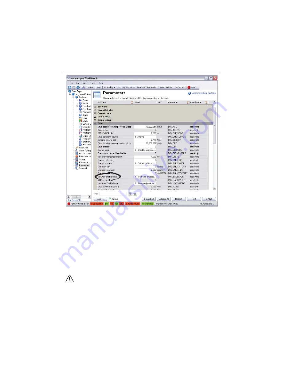
Figure 22 shows the AKD WorkBench parameters page.
Figure 22.
AKD WorkBench Parameters Page
11. Activate the software enable on the drive by clicking the
Enable
button on the
AKD
Overview
page or on the toolbar. Figure 17 shows the location of the
Enable
button.
12. Save all configuration changes to the drive by clicking the
Save to Drive
toolbar button
shown in Figure 17.
Step 6: Ena
b
le and Test the Drive using La
b
VIEW
Use the Interactive Test Panel to test and debug your motion system and configuration settings
on the selected axis. With the Interactive Test Panel you can perform a simple straight-line
move, monitor feedback position and position error information, I/O and move status
information, change move constraints, get information about software errors and faults,
and view position or velocity plots of the move.
Caution
The test parameters in this steps assume that the units have been scaled to
revolutions as described in the preceeding step. If the motor is already connected to
a mechanical system, ensure that moving the motor shaft for 10 revolutions at
1 revolution per second will not damage any components.


