National Instruments 6034E, User Manual
The National Instruments 6034E is a high-quality data acquisition card that offers precise measurements for industrial and scientific applications. To fully utilize its features, make sure to download the user manual for free from manualshive.com. This comprehensive manual will guide you through setup, operation, and troubleshooting of the device.
Share
Download


Reviews:
No comments
Related manuals for 6034E

Perfect Binder D1
Brand: Canon Pages: 99

LP-PCI/P
Brand: Lanpro Pages: 5

Slimline E
Brand: Cidron Pages: 27
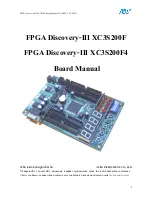
Discovery-III XC3S200F
Brand: Apex Instrument Pages: 18

GV-R699D5-4GD-B
Brand: Gigabyte Pages: 32

TRSH 868 B
Brand: Sminn Pages: 2

MSM8C104EX
Brand: Kontron Pages: 40

PCM-3521
Brand: Aaeon Pages: 21

Ultra Contact Label
Brand: PakSense Pages: 23

3DVision-PAGP
Brand: Elitegroup Computer Systems Pages: 16

GV-N560448-13I
Brand: Gigabyte Pages: 34

EX-44088
Brand: Exsys Pages: 6

KAAN Standard
Brand: Kobil Pages: 3

Traveldrive 1000&1
Brand: Hama Pages: 22

VISTA T100 - START UP GUIDE
Brand: COMPRO Pages: 32

UCD-2 VX1
Brand: Unigraf Pages: 23

Imperial Digiplex Evo R915
Brand: Paradox Pages: 4

ATKey.BLE
Brand: AuthenTrend Pages: 17


