background image

NARVON

3

INSTALLATION

UNPACKING

POSITIONING

ELECTRICAL CONNECTION

1.  Remove cardboard and plastic covering.

2.  Make sure that the machine has not been damaged.

3. 

Remove the plastic film from all the stainless steel panels.

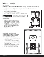
4.  Before operating, remove the green plastic plug(s) from the tap(s). (Fig. 1)

1.  Place the machine on a sturdy horizontal surface.

2.  For improved ventilation, maintain a distance of 6 

in. between the unit and walls or other obstacles. 

Increase the distance if the obstacles are a heating 

source. (Fig. 2)

3.  Leave 60 in. of free space in front of the machine 

to allow for easy use and maintenance. (Fig. 2)

4.  Leave 10 in. of free space above the machine to 

allow for removal of lids. (Fig. 2)

5.  When the machine is in place, adjust the rubber 

legs to level.

1.  Make sure that the machine is properly connected 

to an efficient grounding system, in compliance with 

current safety standards;

2.  Make sure that the voltage is in accordance with 

what is indicated on the “serial number” tag applied 

on the chassis.

3. 

The current available is sufficient for the maximum 

required by the machine;

4.  If needed, use only approved multiple outlets, in 

compliance with current safety standards

5.  If in doubt, consult only specialized technicians.

6.  By law, the machine must always be grounded.

If in doubt, consult a specialized electrical technician. 
Before inserting the plug into the electrical outlet, 

carefully read the following precautions:

In order to prevent the oil contained in the air-tight compressor from flowing into the cooling circuit, it is necessary to 

always carry, store, and handle the machine in a vertical position, following the instructions found on the packaging.
If the machine was accidentally or purposely placed in a non-vertical position during transport, before operating 

the machine it should be kept in a straight position for approximately 30 minutes to allow the oil to flow back


into the compressor.

6”

6”

6”

60”

Fig. 2

Fig. 1

Dispose of packaging materials correctly.

Do not leave within reach of children.

CAUTION

Summary of Contents for 378D2B26

Page 1: ...1 NARVON 2 6 GAL SLIM BOWL REFRIGERATED BEVERAGE DISPENSERS 378D2B26 DOUBLE BOWL 378D4B26 QUADRUPLE BOWL USER MANUAL READ THOROUGHLY BEFORE OPERATION UPDATED 06 2020...

Page 2: ...NARVON...

Page 3: ...not be held responsible for any damage caused by improper use Before installing and operating the machine read this instruction manual carefully Basic safety rules DO NOT touch the machine when hands...

Page 4: ...tch 0 Machine is OFF I Machine is ON B Mixing System Switch es One for Each Bowl 0 Mixer is OFF I Mixer is ON MAIN CONTROLS 378D2B26 378D4B26 Bowls 2 4 Capacity 2 x 2 6 Gal 4 x 2 6 Gal Gas R134a R134a...

Page 5: ...ltage is in accordance with what is indicated on the serial number tag applied on the chassis 3 The current available is sufficient for the maximum required by the machine 4 If needed use only approve...

Page 6: ...he mixing system switch B to ON position There is a switch for each container Fig 4 5 To pour drink out press the drinking glass lightly against lever 1 Every dispenser has been tested and the thermos...

Page 7: ...th lukewarm water For better cleaning and sanitation use a soft brush 4 If the dispenser is out of use for a long period of time remove the power plug and clean all parts carefully keep the dispenser...

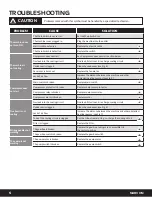
Page 8: ...sources see Fig 2 Compressor does not start Main switch is broken Replace main switch Compressor protector is broken Replace compressor protector Compressor relay is broken Replace compressor relay C...

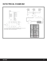
Page 9: ...7 NARVON c Compressor S Exchanger F Fan motor Bc Boiler collector E 1 2 3 Evaporator D Distributor Ca Capillary 1 Drain Line 2 Liquid Line 3 Suction Line T Thermostat ELTECTRICAL DIAGRAM...

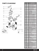
Page 10: ...ompressor 36 40lt 110V 48 404 Fan Motor Comp 220 48 405 Fan Motor Comp 110 48 72 01 Fan motor 10W 220 h84 48 71 01 Fan motor 10W 110 h84 54 150 Rubber Leg 58 775 OR for Stainless Steel Tap 63 234 01 C...

Page 11: ...has been removed or altered Damage or failure due to improper installation improper utility connection or supply and issues resulting from improper ventilation or airflow Defects and damage due to imp...

Reviews: