Montageanleitung für Fachpersonal
Montage
4.1. Montage des Bedienteils
Die Montage des jeweiligen Bedienteils wird im Nahbereich des Infrarotstrahlers
empfohlen.
1. An der gewünschten Position ist ein runder Ausschnitt (Durchmesser 25 mm)
mit z.B. einem Lochbohrer vorzusehen (siehe Abb. 1).
Abb. 1
Installation instructions for qualified personnel
P. 9/20
EN
2.
Carefully remove the selector wheel of the control unit.
3.
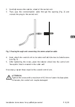
Then, pass the communication cable through the opening (Fig. 2) and
connect the plug to the control unit.
4.
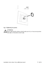
Next, attach the control unit to the cabin wall with the two included screws
(see Fig. 3).
5.
After tightening the screws, place the selector wheel into the control unit
‘base plate’ that is screwed to the cabin wall.
Fig. 2 Passing through and connecting the communication cable
If necessary, repeat these steps for the second control unit.
ATTENTION
Tighten the screws with a maximum of 0.2 Nm to fasten the base plate.
Otherwise, the control unit may be damaged.


