INSTALLATION
SECTION 2
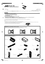
Figure 2-9
2.4.2.5 Autopilot and Additional Indicator Loads
NAV units autopilot output characteristics are shown in Table 2.4.
All autopilot and indicator drives from a NAV are referenced to the +4V REFERENCE line (Pin 29).
Therefore, do not ground any of the connector pins in Table 2.4.
TABLE 2.4 AUTOPILOT OUTPUT CHARACTERISTICS
MODE
FUNCTION
PINS
LOADING
OUTPUT
VOR Left-Right
To-From
28 and 29
10 and 19
One, 1K ohm
One, 1K ohm
150mV for 10
°
course change
250mV at full TO or FROM
LOC Left-Right
Warning-TO
28 and 29
10 and 29
One, 1K ohm
One, 1K ohm
90mV for .093 ddm*
250mV at full TO
GS
Up-Down
Warning-GS
29 and 30
11 and 29
One, 1K ohm
One, 1K ohm
78mV for .091 ddm*
250mV at no GS Flag
* ddm - Difference in depth of modulation.
2.4.2.6 Dimmer Control Adjustment
The NAV122D has a two step dimming circuit. This dimming compares the balance of the pilot lights to
the display. As pilot lights are dimmed by means of aircraft dimmer this diplay will dim. The display’s
intensity can be adjusted by varying R103 located on top left hand control behind mounting screw.
2-17
Summary of Contents for NAV122D
Page 2: ......
Page 4: ...THIS PAGE INTENTIONALLY LEFT BLANK...
Page 22: ...NARCO AVIONICS NAV122D NAV122D GPS 4 2 8...
Page 29: ...INSTALLATION SECTION 2 OR EQUIVALENT FIGURE 2 8 POWER INPUT CONNECTIONS 2 15...
Page 40: ......