Napoleon Torch GSST8N and Installation And Operation Instructions Manual Download Page 15

15

W415-0689 / 06.25.08

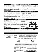
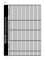
TROUBLE SHOOTING GUIDE

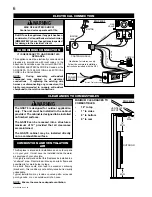
BEFORE ATTEMPTING TO TROUBLESHOOT, PURGE YOUR UNIT AND INITIALLY LIGHT 

THE IGNITOR AND THE MAIN BURNER WITH THE GLASS DOOR REMOVED.

O

S

A

CERAMIC
BODY

ELECTRODE

HIGH
VOLTAGE 
IGNITION
CABLE

1

/

8

GAP

SENSOR

SYMPTOM

PROBLEM

TEST SOLUTION

Electrode sparks, 
burner ignites,  
electrode continues 
to spark for 
complete 7 seconds, 
burner shuts down.

Hot and neutral wires are 
reversed at control module.

Sensor / 

fl

 ame not 

connecting

- Connect the hot wire to the black wire.  Connect the neutral 
wire to the white wire.

- Raise electrode / sensor up into 

fl

 ame 1/4” above the burner.

Flame length 
consistently too 
large or too small.  
Carboning occurs.

Unit is over-

fi

 red or under-

fi

 red.

- Check pressure readings
- Outlet pressure can be checked by removing cap (A) and 
replacing it with a 1/8” NPT barb 

fi

 tting.  Next, place pressure 

gauge tubing over the 

fi

 tting.  Gauge should read 3.5” W.C. 

for natural gas or 10.0” W.C. for propane.  AFTER TAKING 
PRESSURE READINGS, BE SURE TO REPLACE CAP TO 
RESEAL. DO NOT OVER-TORQUE.
- Leak test with a soap and water solution.

Carbon is being 
deposited on glass, 
and combustion 
chamber surfaces.

Air shutter has become 
blocked.

- Ensure air shutter opening is free of lint or other obstructions.

Flame is impinging on the 
combustion chamber.

- Open air shutter to increase the primary air.
- Check the input rate: check the manifold pressure and ori

fi

 ce 

size as speci

fi

 ed by the rating plate values.

White / grey 

fi

 lm 

forms.

Sulphur from fuel is being 
deposited on glass, logs 
or combustion chamber 
surfaces.

- Clean the glass with a gas appliance glass cleaner.  

DO NOT 

CLEAN GLASS WHEN HOT.

   If deposits are not cleaned off 

regularly, the glass may become permanently marked.

No gas to the main 
burner; switch is on.

Switch is defective.

- Connect a jumper wire across the wall switch terminals; if main 
burner lights, replace switch.

Burner ori

fi

 ce is blocked.

- Remove stoppage in ori

fi

 ce.

Control valve faulty.

- Replace.

Faulty valve.

- Replace.

Burner will not light, 
ignitor sparks.

No gas at the burner.

- Check that the manual valve is turned on.
- Replace the valve.

Out of propane gas.

- Fill the tank.

Electrode does not 
spark.  Burner does 
not light.

GFCI has been tripped.

- Push reset button (red) on the face of the GFCI.

Ignitor 
will 
not 
spark.

No spark at ignitor.

- Check the power source. (ie. fuse, circuit breaker, GFCI resent 
button.)
- Check that the wire is connected to both the ignitor and the 
control module.
- Check that the spark is not jumping to ignitor cover.
- Replace the wire if the wire insulation is broken or frayed.
- Replace the electrode if the ceramic insulator is cracked or 
broken.

Spark gap is incorrect.

- Spark gap should be 0.125” (1/8” approx.) from the electrode 
tip to the sensor tip.

Remote wall switch 
is in “OFF” position; 
burner comes on.

Wall switch is mounted 
upside down.

- Reverse.

Remote wall switch is 
grounding.

- Replace.

Remote wall switch wire is 
grounding.

- Check for ground (short); repair ground or replace wire.

Faulty wire.

- Replace.

Summary of Contents for Torch GSST8N and

Page 1: ...h any electrical switch do not use any phone in your building Immediately call your gas supplier from a neighbour s phone Follow the gas supplier s instructions If you cannot reach your gas supplier c...

Page 2: ...from hot surfaces Any safety screen or guard removed for servicing must be replaced prior to operating the enclosure It is imperative that the control compartments burners and circulating blower and...

Page 3: ...t be responsible for installation labour or any other costs or expenses related to the reinstallation of a warranted part and such expenses are not covered by this warranty Notwithstanding any provisi...

Page 4: ...rating shall be reduced at the rate of 4 for each additional 1 000ft This appliance is only for use with the type of gas indicated on the rating plate This appliance is not convertible for use with o...

Page 5: ...The access to the gas inlet is located in the bottom of the cabinet 3 The shut off valve flex connector assembly must always be contained within the cabinet 4 When flexing any gas line support the ga...

Page 6: ...IT WARNING The GSST8 is designed for outdoor application only The unit must be installed in the cabinet provided The cabinet is designed to be installed on finished surfaces The GSST8 can be recessed...

Page 7: ...the metre regulator assembly to a maximum vertical distance of 15 ft H 3 FEET 3 FEET Clearance to a service regulator vent outlet I 12 INCHES 9 INCHES Clearance to a non mechanical air supply inlet t...

Page 8: ...nting surface 3 Start the fasteners into each of the six remaining mounting holes Align the keyholes of the frame to the heads of the fasteners and slide the frame down onto the fasteners Ensure the f...

Page 9: ...ide the appliance before operation FIGURE 9 GLASS RETAINERS GASKET GLASS TOP FIGURE 11 B O T TOM DOOR RETAINER T O P DOOR FLANGE SECURING THE DOOR IN PLACE When shipped the door is secured with two hi...

Page 10: ...o be secured use two screws in the holes provided behind the control door Insert the door stop chain into the receiving slot in the control door Then insert the door chain into the receiving slot in t...

Page 11: ...ht TL Top left and BL bottom left 6 Secure the wires into the clips at both sides and the bottom of the frame Use the extra clips provided to retain any loose wires 7 Re attach frame onto unit 8 Open...

Page 12: ...BE TURNED OFF AT THE LP GAS SUPPLY CYLINDER WHEN THIS APPLIANCE IS NOT IN USE DO NOT STORE OR USE GASOLINE OR OTHER FLAMMABLE VAPORS AND LIQUIDS IN THE VICINITY OF THIS OR ANY OTHER APPLIANCE IMPROPER...

Page 13: ...rify proper operation after servicing This appliance should be inspected before use and at least annually by a qualified service person The appliance area must be kept clear and free of combustible ma...

Page 14: ...EALANT 25 W573 0007 HIGH TEMPERATURE SEALANT 26 W175 0270 CONVERSION KIT NG TO LP 27 W175 0274 CONVERSION KIT LP TO NG Contact your dealer for questions concerning prices and availability of replaceme...

Page 15: ...re and orifice size as specified by the rating plate values White grey film forms Sulphur from fuel is being deposited on glass logs or combustion chamber surfaces Clean the glass with a gas appliance...

Page 16: ...16 W415 0689 06 25 08 Fireplace Service History This fireplace must be serviced annually depending on usage DATE DEALER NAME SERVICE TECHNICIAN NAME SERVICE PERFORMANCE SPECIAL CONCERNS...

Reviews: