Napoleon Torch GSST8N and Installation And Operation Instructions Manual Download Page 11

11

W415-0689 / 06.25.08

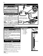
LK8 LIGHT INSTALLATION (OPTIONAL)

1

. Turn off the electrical and gas supply to the appliance.

2

. Remove the frame from the unit by removing the the 2 stainless 

steel hex head securing screws from the bottom and lifting the 
frame off of the top trim bracket. 

3

. Lay the frame down on its front, being careful not to scratch the 

fi

 nish.

4

. Starting at the top of the frame, take one light assembly and 

carefully snap it into place in the hole provided.  Repeat for each of 
the light assemblies.  The wires on the top 2 light assemblies will 
need to be fed in behind the heat shields.

Note: When installing the light kit be careful not to scratch 
your 

fi

 ngers on any of the exposed screws in the frame.

5.

  Connect the light assemblies to the appropriate 

fl

 ags on the wire 

harness.  The wire harness is labeled (TR) top right, (BR) bottom 
right (TL) Top left and (BL) bottom left.

6. 

Secure the wires into the clips at both sides and the bottom of the 

frame.  Use the extra clips provided to retain any loose wires.

7.

 Re-attach frame onto unit. 

8

. Open the control panel door, leave the wires connected to the 

ON/OFF switch and place the transformer into the bottom of the 
unit.  Plug the transformer into the receptacle.

9.

 Attach one of the wire leads from the transformer to the lead on 

the wire harness labeled “TRANS”, and the other to the ON/OFF 
switch.  Attach the last lead on the wire harness labeled “SWI” to 
the ON/OFF switch.  

10.

 Close the control panel door. 

11.

 Turn on the gas supply and electrical power.

ACCENT GLASS INSTALLATION

Carefully sprinkle the accent glass onto the glass support 
evenly.  Ensure no glass falls into the burner area.  If this 
happens, insert a clean bag into your vacuum cleaner and 
vacuum out the accent glass.  Replacement accent glass 
can be purchased from your authorized dealer.

GLASS
SUPPORT

ACCENT
GLASS

BURNER

FIGURE 16

TR

TL

TRANS

SWI

CLIPS X 5

BR

BL

FIGURE 17

Summary of Contents for Torch GSST8N and

Page 1: ...h any electrical switch do not use any phone in your building Immediately call your gas supplier from a neighbour s phone Follow the gas supplier s instructions If you cannot reach your gas supplier c...

Page 2: ...from hot surfaces Any safety screen or guard removed for servicing must be replaced prior to operating the enclosure It is imperative that the control compartments burners and circulating blower and...

Page 3: ...t be responsible for installation labour or any other costs or expenses related to the reinstallation of a warranted part and such expenses are not covered by this warranty Notwithstanding any provisi...

Page 4: ...rating shall be reduced at the rate of 4 for each additional 1 000ft This appliance is only for use with the type of gas indicated on the rating plate This appliance is not convertible for use with o...

Page 5: ...The access to the gas inlet is located in the bottom of the cabinet 3 The shut off valve flex connector assembly must always be contained within the cabinet 4 When flexing any gas line support the ga...

Page 6: ...IT WARNING The GSST8 is designed for outdoor application only The unit must be installed in the cabinet provided The cabinet is designed to be installed on finished surfaces The GSST8 can be recessed...

Page 7: ...the metre regulator assembly to a maximum vertical distance of 15 ft H 3 FEET 3 FEET Clearance to a service regulator vent outlet I 12 INCHES 9 INCHES Clearance to a non mechanical air supply inlet t...

Page 8: ...nting surface 3 Start the fasteners into each of the six remaining mounting holes Align the keyholes of the frame to the heads of the fasteners and slide the frame down onto the fasteners Ensure the f...

Page 9: ...ide the appliance before operation FIGURE 9 GLASS RETAINERS GASKET GLASS TOP FIGURE 11 B O T TOM DOOR RETAINER T O P DOOR FLANGE SECURING THE DOOR IN PLACE When shipped the door is secured with two hi...

Page 10: ...o be secured use two screws in the holes provided behind the control door Insert the door stop chain into the receiving slot in the control door Then insert the door chain into the receiving slot in t...

Page 11: ...ht TL Top left and BL bottom left 6 Secure the wires into the clips at both sides and the bottom of the frame Use the extra clips provided to retain any loose wires 7 Re attach frame onto unit 8 Open...

Page 12: ...BE TURNED OFF AT THE LP GAS SUPPLY CYLINDER WHEN THIS APPLIANCE IS NOT IN USE DO NOT STORE OR USE GASOLINE OR OTHER FLAMMABLE VAPORS AND LIQUIDS IN THE VICINITY OF THIS OR ANY OTHER APPLIANCE IMPROPER...

Page 13: ...rify proper operation after servicing This appliance should be inspected before use and at least annually by a qualified service person The appliance area must be kept clear and free of combustible ma...

Page 14: ...EALANT 25 W573 0007 HIGH TEMPERATURE SEALANT 26 W175 0270 CONVERSION KIT NG TO LP 27 W175 0274 CONVERSION KIT LP TO NG Contact your dealer for questions concerning prices and availability of replaceme...

Page 15: ...re and orifice size as specified by the rating plate values White grey film forms Sulphur from fuel is being deposited on glass logs or combustion chamber surfaces Clean the glass with a gas appliance...

Page 16: ...16 W415 0689 06 25 08 Fireplace Service History This fireplace must be serviced annually depending on usage DATE DEALER NAME SERVICE TECHNICIAN NAME SERVICE PERFORMANCE SPECIAL CONCERNS...

Reviews: