


22
W415-0661 / 12.07.07
1.
Move the fi replace into position. Measure the vent length required
between terminal and fi replace taking into account the additional length
needed for the fi nished wall surface and any 1¼" overlaps between
venting components.
2.
Apply high temperature sealant W573-0007 (not supplied) to
the outer edge of the exhaust vent pipe of the fi replace. Attach
the fi rst vent component and secure using 3 self tapping screws.
Repeat using air intake vent pipe and seal using high temperature
sealant W573-0002 (not supplied).
3.
Holding the air terminal (lettering in an upright, readable posi-
tion), insert into both vent pipes with a twisting motion to ensure
that both the terminal sleeves engage into the vent pipes and
sealant. Secure
the terminal to the
exterior wall and
make weather tight by
sealing with caulking
(not supplied).
The air terminal mounting
plate may be recessed into
the exterior wall or siding by
1½", the depth of the return
fl ange.
USING RIGID VENT COMPONENTS
HORIZONTAL AIR TERMINAL INSTALLATION
ATT
ENT
ION
-CH
AUD
CAU
TIO
N -
HO
T
EXHAUS
T
AIR INT
AKE
VENT PIPE
2” OVERLAP
HI-TEMP
SEAL
ANT
CAULK
ING
#10 X 2”
SCREWS
FIGURE 60
EXTENDED HORIZONTAL AND CORNER
AIR TERMINAL INSTALLATION
1.
Follow the instructions for "Horizontal Air Terminal Installations",
items 1 to 3.
2.
Continue adding components alternating inner and outer venting.
Ensure that all exhaust vent-
ing and elbows have suffi cient
vent spacers attached and each
component is securely fastened to
the one prior. Attach the exhaust
telescopic sleeve to the vent run.
Repeat using a air intake vent pipe
telescopic sleeve. Secure and seal
as before. To facilitate completion,
attach exhaust and air intake vent
pipe couplers to the air terminal.
3.
Install the air terminal.
See
item 3 of the Horizontal Air
Terminal Installation.
Extend the
exhaust telescopic sleeve; connect to the air terminal assembly.
Fasten with self tapping screws and seal. Repeat using the air
intake vent pipe telescopic sleeve.
BGD36CF SHOWN
FIGURE 61
EXHAUST
VENT PIPE
AIR INTAKE
VENT PIPE
INNER
VENT PIPE
HIGH
TEMPERATURE
SEALANT
AIR
TERMINAL
CONNECTOR
VERTICAL VENTING INSTALLATION
FIGURE 62
FIGURE 63
4
.
Apply high temperature sealant to the
outer edge of the of the outside pipe of
the air terminal connector. Slip a coupler
over the air intake collar and secure as
before. Trim the air intake coupler even
with the exhaust coupler end.
5
.
Thread the air terminal connector /
pipe assembly down through the roof
support and attach, ensuring that the
air terminal will penetrate the roof a
minimum 16" when fastened.
If the attic
space is tight, we recommend threading
the Wolf Steel vent pipe collar or equiva-
lent loosely onto the air terminal assembly as it is passed
through the attic.
The air terminal must be located vertically and
plumb.
6.
Remove nails from the shingles, above and to the sides of
the chimney. Place the fl ashing over the air terminal and slide it
underneath the sides and upper edge of the shingles. Ensure that
the air terminal is properly centered within the fl ashing, giving a
3/4" margin all around. Fasten to the roof. Do NOT nail through the
lower portion of the fl ashing. Make weather-tight by sealing with
caulking. Where possible, cover the sides and top edges of the
fl ashing with roofi ng material.
7.
Align the seams of the terminal and air terminal connector,
place the terminal over the air terminal connector making sure the
inner pipe goes into the hole in the terminal. Secure with screws
provided.
8.
Apply a heavy bead of weatherproof caulking 2" above the
fl ashing. Note: Maintain a minimum of 2" space between the air
inlet base and the storm collar. Install the storm collar around the
air terminal and slide down to the caulking. Tighten to ensure that
a weather-tight seal between the air terminal and the collar is
achieved.
9.
Continue adding rigid venting sections, sealing and securing
as above. Attach an exhaust telescopic sleeve to the last section
of rigid piping. Secure with screws and seal. Repeat using an air
intake telescopic sleeve.
10.
REAR VENT APPLICATION: (BGD36CF(G) ONLY:
Before
attaching elbows to the collars on the back of the fi replace,
1½" will need to be trimmed off the exhaust pipe collar.)
Run a bead of high temperature sealant
W573-0007 (not supplied) around the
outside of the exhaust collar. Attach
the exhaust elbow to the exhaust
collar and secure with 3 screws. Run
a bead of high temperature sealant
W573-0002 (not supplied) around
the outside of the air intake collar.
Attach the air intake elbow to
the air intake collar and secure
with 3 screws. Pull the exhaust
telescopic sleeve a minimum 2"
onto the elbow. Secure with 3 screws. Repeat with the air intake
telescopic sleeve.
TOP VENT APPLICATION:
Run a bead of high temperature seal-
ant W573-0007 (not supplied) around the outside of the exhaust
on the fi replace. Pull the exhaust telescopic sleeve a minimum of
2" onto the collar. Secure with 3 screws. Repeat with the air intake
telescopic sleeve.
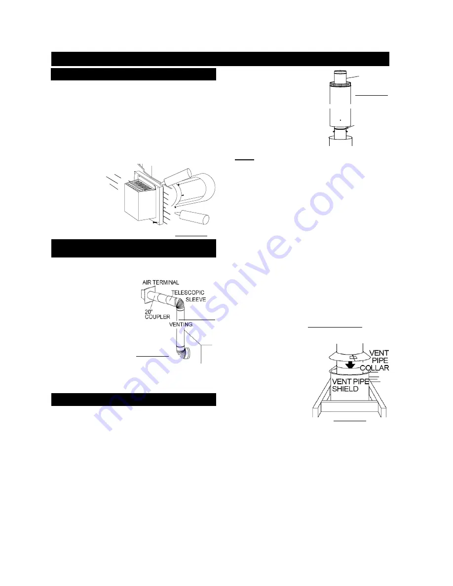
11.
In the attic, slide the vent pipe collar down to cover up the open
end of the vent pipe shield and tighten. This will prevent any ma-
terials, such as insulation, from fi lling up the 1" air space around
the pipe.
For safe and proper operation of the fi replace, follow the venting
instructions exactly.
All inner exhaust and outer intake vent pipe joints may be
sealed using either high temperature sealant W573-0002 or
high temperature Mill Pac W573-0007 with the exception of the
fi replace exhaust fl ue collar which must be sealed using Mill
Pac (not supplied).
1.
Move the fi replace into position.
2.
Fasten the roof support to the roof using the screws provided.
FIGURE 56.
The roof support is optional. In this case the venting is
to be adequately supported using either an alternate method suit-
able to the authority having jurisdiction or the optional roof support.
3.
Apply high temperature sealant W573-0002 (not supplied) to
the outer edge of the inner end of the air terminal connector. Slip a
coupler a minimum of 2" over the exhaust collar and secure using
3 screws.
NorthlineExpress.com
http://www.northlineexpress.com
Toll-Free 1-866-667-8454