


X
GEM-P1664EX Programming Instructions
L
NAPCO Security Systems
Page 44
WI1387 7/05
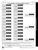
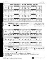
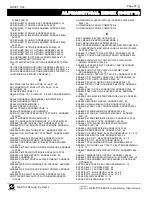
AREA ARMING OPTIONS (ADDRESS 1469-1472)
PRIORITY AREA ARMING:
1. Select option from the table shown.
2. Enter in corresponding right digit address location (left digit is not used).
NOTE:
Dark shaded data value box shows option not available.
3. Press
U
or
D
to save.
PRIORITY ARMING/AREA 1
OPTION
LEFT
RIGHT
blank (•)
blank (•) Not Used
blank (•)
1
Enabled
DATA ENTRIES
PRIORITY ARMING/AREA 2
OPTION
LEFT
RIGHT
blank (•)
blank (•) Not Used
blank (•)
1
Enabled
DATA ENTRIES
Priority
ADDRESS 1469
Arming
LEFT
RIGHT
Area 1
blank (•)
[Default = blank (•) blank (•)]
Priority
ADDRESS 1470
Arming
LEFT
RIGHT
Area 2
blank (•)
[Default = blank (•) blank (•)]
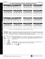
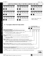
ZONE INTEGRATION TIME (ADDRESS 2062)
Zone Integration Time
:
The panel Zone Integration (Response) time can be adjusted to a
new global value. Address 2062 accepts three decimal digits which are multiplied by 10 milli-
seconds to get a new value that replaces the default value of 750ms. If the location is set to
000, the system will default to 750ms internally. The maximum value is 255. If a value above
255 is entered the system will display 000 to request a re-entry.
Note:
Only the panel zones’ integration times are programmable. EZM’s will continue to use
either 50 or 750 ms as selected by jumpers on the EZM. In addition, zone responses are en-
abled only when armed.
Di
rec
t
A
d
dre
ss
P
rogr
am Mode
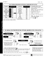
PRIORITY ARMING/AREA 1
OPTION
LEFT
RIGHT
blank (•)
blank (•) Not Used
blank (•)
1
Enabled
DATA ENTRIES
PRIORITY ARMING/AREA 2
OPTION
LEFT
RIGHT
blank (•)
blank (•) Not Used
blank (•)
1
Enabled
DATA ENTRIES
Priority
ADDRESS 1471
Arming
LEFT
RIGHT
Area 3
blank (•)
[Default = blank (•) blank (•)]
Priority
ADDRESS 1472
Arming
LEFT
RIGHT
Area 4
blank (•)
[Default = blank (•) blank (•)]
ADDRESS 2280
LEFT
RIGHT
[Default = 075 x 10ms = 750ms]
Zone
Integration
Time (x 10ms)
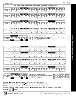
ZONE INTEGRATION TIME
TIMEOUT
LEFT
RIGHT
blank (•)
blank (•)
(0) 1/100 sec. = 0 will
default to 750ms.
blank (•)
2
(2) 1/100 sec. = 20ms.
blank (•)
3
(3) 1/100 sec. = 30ms.
blank (•)
4
(4) 1/100 sec. = 40ms.
blank (•)
5
(5) 1/100 sec. = 50ms.
blank (•)
6
(6) 1/100 sec. = 60ms.
blank (•)
7
(7) 1/100 sec. = 70ms.
blank (•)
8
(8) 1/100 sec. = 80ms.
F
F
(255) 1/100 sec. = 2.55
sec.
DATA ENTRIES
1. Select delay/timeout from the table shown at left.
2. Enter in corresponding address locations above (left and right digits).
3. For a desired delay/timeout not listed do the following:
A. Choose a desired delay/timeout, ex: 20
B. Divide it by 16
4. Press
U
or
D
to save.
1 Quotient Left Digit
16 20
16
4 Remainder Right Digit


