791-7136 3 12/11/18
OPERATING MANUAL FOR 791-7136
FUEL TANK SADDLE ADAPTER SETUP
PLEASE REFER TO THE EXPLODED VIEW DRAWING IN THIS MANUAL IN ORDER TO IDENTIFY PARTS
AND PROPER ASSEMBLY CONFIGURATION.
1. Install the #13 arm assemblies in the #12 base assembly as shown in the exploded view drawing on page 5. Secure them in place by
screwing in the #11 locking knobs as shown in the drawing.
2. Install the #15 height adjustment tubes in the #13 arm assemblies and secure them to the arm assemblies at the desired height with the
#14 detent pins.
3. The #16 support pad assemblies have two mounting locations which enable the pads to be located in towards the center of the adapter
or further away from the center of the adapter depending on the fuel tank size and configuration. Secure the #16 support pad assemblies
to the top holes of the #15 height adjustment tubes with the #14 detent pins.
4. Feed the #7 ground screw through the #4 flat washer, the electrical connector ends of both #2 ground wires, and through #5 hex nut,
and tighten the #7 ground screw in the #12 base assembly. It may be necessary to tighten the #5 nut up against the electrical connectors
to ensure the connectors are not loose.
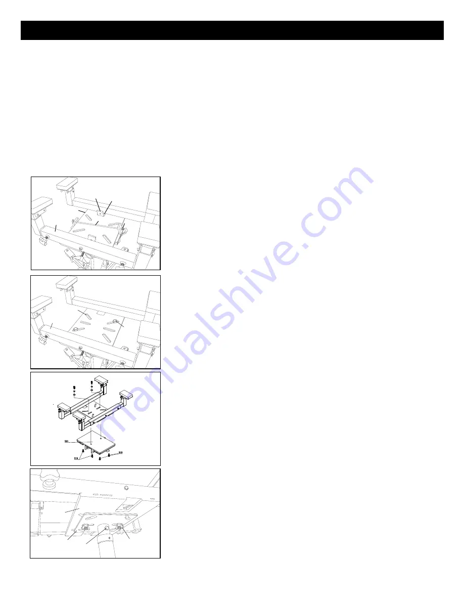
INSTALLING THE FUEL TANK SADDLE ADAPTER ON UNDER HOIST TRANSMISSION JACKS
This saddle adapter is designed to fit on three types of transmission jack saddles
:
TYPE 1 - The NAPA model 791-7140 and 791-7200 under hoist transmission
jacks are equipped with the popular ratchet adjustment arms in their saddles. See
figure 1. The center of the saddle adapter has two rectangular shaped holes to
accept two of the ratchet arms, and the opposite ratchet arms will fit against
the perimeter edge of the center portion of the saddle adapter. Center the
saddle adapter on the jack's saddle and tighten the jack's ratchet arms against
the adapter. The #6 lock rod can be fed through the holes at the top of two of
the ratchet arms and secured with the #4 flat washers and #3 wing nuts as
shown in figure 1. This secures the saddle adapter to the jack's saddle.
TYPE 2 - Some transmission jacks are equipped with flat saddles with arms
that can be temporarily removed. See Figure 2. The saddle adapter can be
placed on the top of the jack's flat saddle and centered in a position where
the oval holes in the saddle adapter align with two hole locations in the jack's
saddle. The two hole locations should be directly across from each other so
the jack's saddle and saddle adapter can be secured together with hardware kit
provided provided. If the provided hardware will not work, use grade 5 hardware
or the metric equivalent to secure the two plates together.
This saddle adapter is designed to fit on 791-9006.
TYPE 3 - Some jacks will have to have their stock saddles removed and
replaced with the #10 adapter plate included with the saddle adapter. The
adapter plate is secured to the jack's ram by tightening the #9 screw at the
base of the adapter plate. See Figure 3. Follow the assembly instructions for
TYPE 2 jacks to secure the saddle Adapter to the adaptor plate.
RATCHET
ADJUSTMENT
ARMS
RECTANGULAR
SHAPED HOLE
LOCK
ROD
FLAT
WASHER &
WING NUT
FUEL TANK
SADDLE
ADAPTER
PERIMETER
EDGE
Figure 1
OVAL
HOLES
HARDWARE
SUPPLIED OR
METRIC
EQUIVALENT
Figure 2
FUEL TANK
SADDLE
ADAPTER
FUEL TANK
SADDLE
ADAPTER
ADAPTER
PLATE
INCLUDED
TIGHTEN
SCREW
CARRIAGE
BOLTS, FLAT
WASHERS AND
WING NUTS
Figure 3


