Technical manual
SMCP33
Connections and circuits
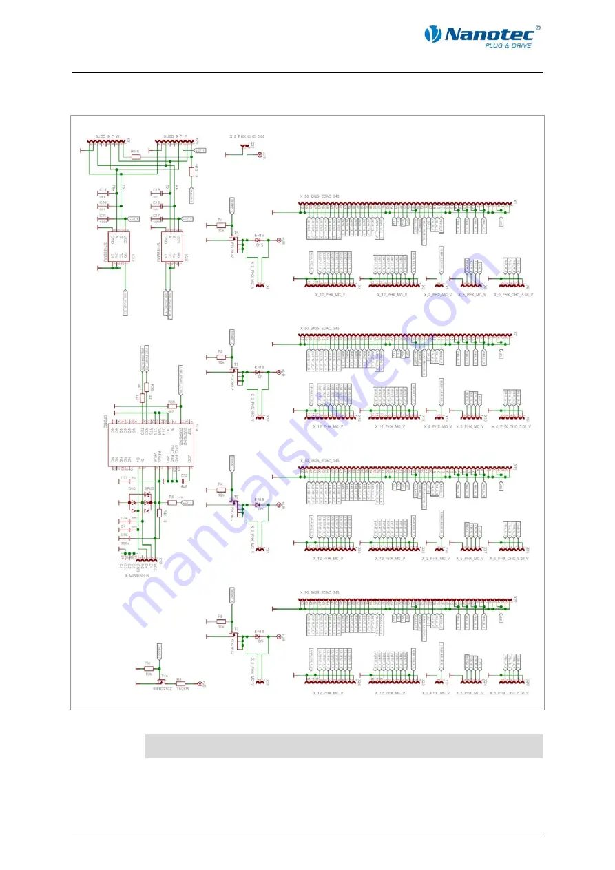
Connection diagram
Note:
The connection diagram is available for download on www.nanotec.de.
12
Issue: V 1.1 - 01.02.2010
Page 1: ...Technical Manual Stepper motor control SMCP33 NANOTEC ELECTRONIC GmbH Co KG Gewerbestra e 11 D 85652 Landsham near Munich Germany Tel 49 0 89 900 686 0 Fax 49 0 89 900 686 50 info nanotec de...
Page 2: ...e 11 D 85652 Landsham Pliening Germany Tel 49 0 89 900 686 0 Fax 49 0 89 900 686 50 Internet www nanotec com All rights reserved MS Windows 2000 XP Vista are registered trademarks of Microsoft Corpora...
Page 3: ...usively intended as a technical description of the product and as commissioning instructions The warranty is exclusively for repair or replacement of defective equipment according to our general terms...
Page 4: ...1 Pin assignment SMCP33 9 3 2 SMCP33 EVA evaluation board 11 3 3 Inputs and outputs I O 13 3 4 Brake connection 15 3 5 Ballast connection 15 3 6 Encoder connection 16 3 7 Stepper motor connection 17...
Page 5: ...llowing functions Microstep 1 1 1 64 final output stage 0 014 step resolution Closed loop current control sinusoidal commutation via the encoder Powerful DSP microprocessor for flexible I O Sequence p...
Page 6: ...be run autonomously without a superordinate controller The programs can be created compiled directly and written to the controller with the free NanoJEasy editor More detailed information can be found...
Page 7: ...Install the NanoPro control software on your PC See the separate manual on NanoPro Download of www nanotec com 2 Plug the SMCP33 into the motherboard SMCP33 EVA evaluation board Detailed information...
Page 8: ...is connected can be found in the device manager of your Windows PC System Control System Hardware 9 Select the 115200 bps entry in the Baud rate selection field 10 Select the Mode tab 11 Click on the...
Page 9: ...Technical manual SMCP33 Connections and circuits 3 Connections and circuits 3 1 Pin assignment SMCP33 Pin assignment Issue V 1 1 01 02 2010 9...
Page 10: ...9 Track B 20 5 V Encoders 21 Temp motor 22 Brake Brake output 23 24 Ballast Ballast output 25 RS 485 Rx 26 RS 485 Rx 27 RS 485 Tx 28 RS 485 Tx RS 485 connection 29 30 GND Earth 0 V 31 Analogue In 1 An...
Page 11: ...motherboard for the SMCP33 plug in device card It can be used for the rapid commissioning of four stepper motors via a pre wired RS485 network and a PC connection All inputs and outputs available in...
Page 12: ...Technical manual SMCP33 Connections and circuits Connection diagram Note The connection diagram is available for download on www nanotec de 12 Issue V 1 1 01 02 2010...
Page 13: ...als Note The voltage should drop below 2 V for safe switching off and be at least 4 5 V for safe switching on Output circuits The outputs are a TTL output circuit 5 V max 20 mA To be able to test the...
Page 14: ...limit switch Direction Ext limit switch Clock Direction 39 Input 7 40 Input 8 All digital inputs with the exception of the Clock and Direction inputs in the clock directional mode can be freely progr...
Page 15: ...nnection Function The ballast output is used by the controller to indicate overvoltage at the supply Circuit on the motherboard The motherboard should have a circuit that protects the controller again...
Page 16: ...here possible use Nanotec encoders with the order number HEDS HEDL 5541 Xxx If an encoder is not used the Disable mode must be set in the Error correction tab in the Rotation Direction Mode selection...
Page 17: ...age See also data sheet of connected stepper motor colour code of 4 wires Never disconnect the link when operating voltage is applied Never disconnect lines when live Motor with 6 or 8 connections If...
Page 18: ...Technical manual SMCP33 Connections and circuits 18 Issue V 1 1 01 02 2010...
Page 19: ...ser with minimum 4700 F Connect a condenser with 10000 F for motors with flange size 86x86 series ST8918 or greater An operating voltage 50 V will destroy the output stage Mixing up the connections ca...
Page 20: ...VA On the SMCP33 EVA motherboard shown in section 3 2SMCP33 EVA evaluation board four stepper motors can be rapidly commissioned via a pre wired RS485 network and a PC connection For the PC connection...
Page 21: ...erence run the motor travels to an internal reference point at the set minimum speed External Homing During an external reference run the motor travels to a switch connected to the reference input Spe...
Page 22: ...trolled in this operating mode simply with a potentiometer or a joystick 10 V to 10 V Use this mode if you want to use the motor in a simple application Setting a specific speed e g via an external po...
Page 23: ...existent motor number module number is set Set the correct module address See the separate manual on NanoPro The power supply of the SMCP33 is interrupted Check voltage supply switch on if necessary A...
Page 24: ...p Half step Quarter step Fifth step Eighth step Tenth step 32th step 64th step Adaptive microstep 1 128 Step angle 1 8 Operating modes Position Speed Flag position Clock direction Analogue Analogue Po...
Page 25: ...tion depending on the switch on duration current drop set and external cooling area Ambient temperature 0 to 40 C SMCP33 dimensions SMCP33 K dimensions with heat sink A complete set of datasheets is a...
Page 26: ...nt control 5 E Encoder 6 16 External Homing 21 I Input circuits 13 Inputs 14 Internal Homing 21 M Motor connection 17 O Operating modes 21 Operating voltage 19 Output 14 Output circuits 13 P Pin assig...