Technical Manual PD4-E-M (EtherCAT)
5 General concepts
Jerk unit
The jerk unit is Acceleration unit per second.
Conversion factor for jerk
The factor n for the jerk is calculated from the numerator (60A2
h
:01
h
) divided by the denominator
(60A2
h
:02
h
).
n
jerk
=
60A2
h
:02
60A2
h
:01
5.4 Limitation of the range of motion
The digital inputs can be used as limit switches, as is described in chapter Digital inputs, if you
activate this function for the inputs. The controller also supports software limit switches.
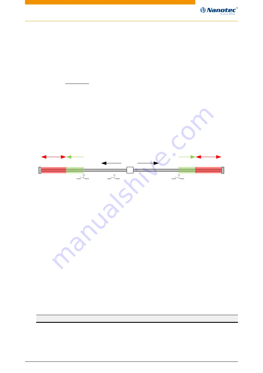
5.4.1 Tolerance bands of the limit switches
negative
direction
positive
direction
Tolerance-
zone 2056h
Forbidden
area
Tolerance-
zone 2056h
Forbidden
area
negative limit
switch
Positive limit
switch
reference
switch
The previous figure shows the breakdown of the tolerance bands next to the limit switches:
•
The tolerance zone begins immediately after the limit switch. Free movement is possible in this
zone. The length of the zone can be set in object 2056
.
•
If the motor moves into the forbidden range, the controller triggers an immediate stop and it
switches to the fault state, see also State transitions.
5.4.2 Software limit switches
The controller takes into account software limit switches (607D
(Software Position Limit)). Target
positions (607A
) are limited by 607D
h
) may not be larger than the limits
h
. If the motor is located outside of the permissible range when setting up the limit switches,
only travel commands in the direction of the permissible range are accepted.
5.5 Cycle times
The controller operates with a cycle time of 1 ms. This means that data are processed every 1 ms;
multiple changes to a value (e.g., value of an object or level at a digital input) within one ms cannot be
detected.
The following table includes an overview of the cycle times of the various processes.
Task
Cycle time
Application
1 ms
NanoJ application
1 ms
Current controller
31.25 µs (32 kHz)
Version: 1.0.1 / FIR-v1748
45