background image

9

OPERATING AND MAINTENANCE MANUAL

Chapter 5 

- Installation

NRC0020-0200 UL

The data in this manual are not binding and may be changed by the manufacturer without notice. 

Reproduction of this manual, even partial, is strictly prohibited.

5 . 3

E l e c t r i c a l   c o n n e c t i o n s

The unit's connection to the power supply must be made in compliance with laws and prescriptions in force in the place of installation, after 
having consulted the electrical diagram supplied with the unit.
The voltage, frequency and number of phases must comply with the data on the unit's dataplate.
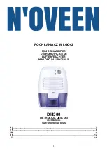
Main distribution systems in the USA:

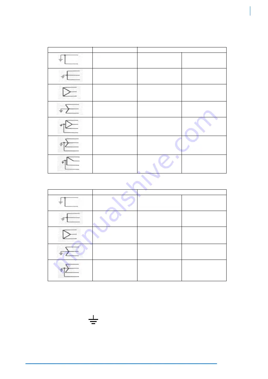
Main distribution systems in Canada:

For the electrical power supply:

1.

To access the electrical panel, remove the lateral screws fixing the top cover to the side panels of the cabinet and remove the front
panel by undoing the screws securing the panel to the base.
To access the electrical panel components undo the nuts fixing its protective cover to the front panel.

2.

Connect the unit (terminal 

 in the electrical panel) to the electrical earthing system of the building;

3.

Make sure the level of protection against indirect contact at the source of the power feeding cable is equivalent at least toNEMA
Type 1;

4.

At the start of the power feeding cable or the power cable supplied with the unit install a device that protects the cable from
overcurrent (short circuits) (refer to the indications in the electrical diagram)
All protection devices must be approved (“listed”) for this purpose.

System

Rated Voltage

User voltage


120

115

110


240/120

230/115

220/110


600
480
240

575
460
230

550
440
220


480

460

440


480/277
208/120

460/266
200/115

440/254
190/110


240/120

230/115

220/110


240/120

230/115

220/110

System

Rated Voltage

User voltage


240
480
600

230
460
575

220
440
550


240/120

230/115

220/110


600
480
240

575
460
230

550
440
220


600
480
240

575
460
230

550
440
220


600/347
480/277

416*/240

208/120

575/332
460/266

400*/230

200/115

550/318
440/254

380*/220

190/110

Summary of Contents for NRC0020-0200 UL

Page 1: ...R e f r i g e r a t e d a i r d r y e r s OPERATING AND MAINTENANCE MANUAL Our contact details www n psi com 38178800655 Original instructions NRC0020 0200 UL...

Page 2: ......

Page 3: ...Location 8 5 2 Piping 8 5 3 Electrical connections 9 Chapter 6 START UP 11 Chapter 7 IDRY ELECTRONIC CONTROLLER 12 7 1 User interface 12 7 1 1 Display 12 7 1 2 Buttons 12 7 1 3 Icons 13 7 2 Main func...

Page 4: ...in the dimensional drawings and refrigerant circuit diagrams in this manual The meaning of each symbol is indicated hereinafter The following warning symbols are to be found on the decals affixed to t...

Page 5: ...long working life If spare parts are needed use exclusively genuine original components Requests for SPARE PARTS and any INFORMATION concerning the dryer must be made to the nearest dealer or service...

Page 6: ...n strictly necessary Handling of dryers must be carried out in compliance with the diagrams given see the final part of this manual The manufacturer does not supply bars belts and lifting hooks with t...

Page 7: ...pted to protect against the toxic fumes that may be given off Before removing any panels or dismantling any parts of the unit perform the following steps Isolate the unit from the electrical power sup...

Page 8: ...max Sum of FLA of all loads INSTALLED POWER P max Sum of the maximum power input of all loads PROTECTION RATING According to European standard UL508A and EN60529 ELECTRICAL DIAGRAM Identifies the elec...

Page 9: ...h the air air section of the thermal mass where it absorbs the heat of the warm and humid compressed air entering the dryer and thereby cools the inlet flow This air air exchanger both reduces the amo...

Page 10: ...lation drawing 1 The inlet and outlet connections are clearly marked see Chapter 1 General Information The piping and connections must be correctly sized and suitable for the working pressure of the a...

Page 11: ...the electrical panel components undo the nuts fixing its protective cover to the front panel 2 Connect the unit terminal in the electrical panel to the electrical earthing system of the building 3 Ma...

Page 12: ...ing ambient temperature according to the chosen installation type see the indications on the electrical diagram Use exclusively copper cables marked UL in compliance with NEC NATIONAL ELECTRICAL CODE...

Page 13: ...see Chapter 7 iDRY Electronic Controller 6 Press button of the control unit Once the programmed delay has elapsed the compressor and fan will start On three phase power supply models make sure the fa...

Page 14: ...ges shown on the LCD display The display messages can be Unit OFF Unit running normal operation High Dew Point temperature BUTTON FUNCTION Displays or edits the set point During programming selects a...

Page 15: ...he display will show the message 0 W The icon indicates compressor operation In the event of sudden power failure when the unit is running the unit will resume operation automatically when the power i...

Page 16: ...ithin the time interval set in parameter the alarm is activated The message is displayed the compressor is shut down and control is suspended To resume normal operation the device must be switched off...

Page 17: ...played Press and hold buttons and for a few seconds until the message flashes on display The keypad is now unlocked NOTE The new value entered is saved to the memory also when you quit programming mod...

Page 18: ...vated on opening of the contact the digital input is activated on closure of the contact oP CL CL X Pr1 Digital input configuration external alarm external shutdown alarm pressure switch remote On Off...

Page 19: ...he instrument off 7 5 2 High and low temperature alarm memorization When the icon illuminates the unit is in alarm status Flashing Alarm active Steady Temperature alarm reset and memorised To check th...

Page 20: ...ic board monitors the signal sent by the capacitive sensor continuously When the condensate level reaches the sensor lower limit the solenoid valve is de energized thereby interrupting condensate drai...

Page 21: ...rom the insulated condensate drain pipe which protrudes from the underside of the dryer The pipe fittings of the condensate drain are supplied in a plastic bag secured to the condensate drain insulate...

Page 22: ...end breaks without any problem In this case remember when the unit is required for duty again to switch the dryer on at least 10 15 minutes before the air compressor 9 2 M a i n t e n a n c e CAUTION...

Page 23: ...n the limit for which the dryer was selected normally 35 40 C 95 104 F When the compressor is running check that its upper part is not too hot more than approximately 50 C 122 F Check that the dryer s...

Page 24: ...sitioning Circuit has insufficient refrigerant charge Isolate the dryer from the air network dismantle the solenoid valve clean the components and refit the valve Air cooled dryers front surface of th...

Reviews: