background image

11

Presentation

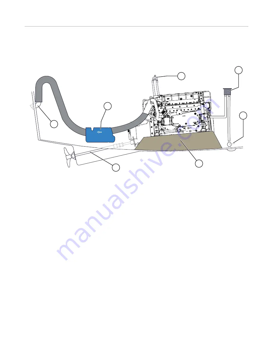
Installation inspection

 I     

Attention! : 

 Your engine must be installed by an authorised shipyard or a qualifi ed Nanni Industries representative in 

accordance with the on board assembly instructions. However, you can check some important points on the installation 
of the engine. 

 1. Engine frame  

The engine frame must be solid and able to absorb all the 
dynamic stress as well as the weight of the engine. It must 
be connected to the hull by an area as large as possible.

The engine must not be at an angle of more than 15° when 
the boat is stopped.  

  2. Propeller shaft  

  The choice of propulsion system must be made according 
to the restrictions arising from the engine, the boat, and the 
use of the boat.

  3. Waterlock exhaust box  

The waterlock must be positioned as close to the engine 
and as low as possible.  

  4. Hull outlet  

  The hull outlet must be located 15cm below the water line. 
The tube between the exhaust box and the hull outlet must 
form a swan-neck shape to avoid any water getting into the 
exhaust system through the hull outlet.

  5. Anti-siphon valve  

Mandatory on boats whose engine is below the waterline. 
The anti-siphon valve must be installed at the end of the 
seawater system before injection in the exhaust elbow and 
must be positioned above the waterline, between 0.5 and 
2 metres.   

  6. Seawater filter  

  This must always be positioned at least 15 cm above the 
waterline.

  7. Through-hull valve  

On yachts and boats that do not go above 12 knots, the 
water inlet must be turned towards the end of the boat.

On motor boats that go over 12 knots, the water inlet must 
be turned forwards the end of the boat.  

  Engine room  

  The temperature inside the engine compartment must not 
exceed 50°C with a maximum difference of 20°C with the 
outside temperature.

Slow boats must have a ventilator fitted. Fresh air from the 
front is circulated from front to back. The front air intake is 
located low down at the front of the engine compartment 
and the outlet high at the back for optimum air circulation.

Electrical installation

An incorrect or faulty electrical installation can cause 
leakage currents that can affect the galvanic protection of 
the engine and damage the engine subsequently.

The installer must ensure to take all necessary precautions 
to protect the engine against corrosion.  


4

3

5

6

2

1

7

Summary of Contents for V6.270

Page 1: ...Instruction manual Marine Diesel engines V6 270 V6 320 V6 350 970315366 01032011 C...

Page 2: ...el system 16 Bleeding the fuel circuit 16 Replacing the fuel filter 16 Replacing the fuel prefilter 17 Draining the water from the fuel prefilter 17 Lubrication circuit 18 Checking the oil level 18 Re...

Page 3: ...your equipment This manual contains important safety indications and information They are as follows I Danger This symbol indicates the risk of accidents and serious personal injury substantial prope...

Page 4: ...e coolant and oil circuit caps when the engine is operational and or hot Never start or run the engine when the oil fill cap is not screwed on as hot oil could spray out If you come into contact with...

Page 5: ...onal I Rotating parts Rotating parts can be extremely dangerous and cause serious injury and even death Do not work on the engine when it is operational If work on the engine when running is absolutel...

Page 6: ...lar attention to the information on personal safety This manual must always be to hand where the engine is used We recommend that you visually check the overall condition of your engine before and aft...

Page 7: ...to the water The different fluids used to run the engine are a health hazard Carefully read the instructions on the packaging of these products and always check that the ventilation in the storage com...

Page 8: ...show the engine oil level This indicator shows the oil pressure The pilot lamp inside the dial is lit and an audible alarm sounds if the oil pressure in the lubrication circuit falls At idle the pres...

Page 9: ...h pressure turbo This alert indicator indicates that the air pressure in the turbocharger is too high If one or more of these lights come on when the engine is running stop the engine except in emerge...

Page 10: ...Oil drain orifice 11 Oil gauge 12 Oil filter 13 Heat exchanger 14 Coolant fill orifice 15 Seawater pump 16 Heat exchanger drain plug 17 Electronic control unit 18 Supports 19 Turbocompressor 20 Hoist...

Page 11: ...iphon valve Mandatory on boats whose engine is below the waterline The anti siphon valve must be installed at the end of the seawater system before injection in the exhaust elbow and must be positione...

Page 12: ...ine is not used regularly turn the ignition and let the engine run at idle until it reaches operating tempera ture Do this at least one time per month when not in use Carry out the following operation...

Page 13: ...ving the engine the time to warm up by idling for several minutes and only run at full speed for short periods of time Stopping the engine Let the engine run at idle in the neutral position for few mi...

Page 14: ...preserve the mechanical qualities of the engine and prolong its service life we recommend you follow the instructions below Use a coolant made of 50 water and 50 antifreeze Use tap water for the mix...

Page 15: ...is required I Attention Do not let oil fuel or grease deposits build up around the engine as they may increase the risk of fire in the engine compartment Check the operation of the different lamps an...

Page 16: ...screw and lock the hand pump B I Attention Avoid draining all the fuel in the filter when bleeding If you have remove the filter and replenish with fuel before replacing it and repeat the bleeding Rep...

Page 17: ...uel prefilter Remove the filter tank A Drain and clean the filter tank Replace the cartridge B and re install the tank Open the fuel valve Drain the feed system then start the engine to check the leak...

Page 18: ...oil until reaching the specified level Fill the oil via the fill orifice situated on the top of the engine Add the oil slowly and wait several minutes before checking the level again This allows the...

Page 19: ...ce A Connect the drain pump to the orifice A Use a pail to collect the extracted oil Pump until the oil has been completely extracted Refill with the new oil the amount of oil to add is indicated in t...

Page 20: ...eceptacle and ensure the fluids are well mixed Coolant filling I Attention Do not check the coolant level when the engine is hot Pressurised coolant can spurt and cause serious burns Carry out this wo...

Page 21: ...under the drain caps A and B then untighten it Let the coolant run out until the exchanger is empty Clean the inside of the heat exchanger by following the instructions below before closing the caps R...

Page 22: ...ter filter The seawater filter is an optional component These instructions are given as an example only Check the condition of the seawater filter with the engine stopped If deposits have formed remov...

Page 23: ...ter intake valve Remove the seawater pump cap A and the seal B then remove the rotor C without damaging it Check the condition of the rotor replace it if even the most minor defect is noted Clean the...

Page 24: ...level of noise made by the engine and purifies the air injected into the combustion chamber If the filter is too clogged replace it If it is not Remove the hose retaining ring and remove the filter Fi...

Page 25: ...d premature discharging notably in wet weather The battery terminals and the cables must be cleaned with a brass brush in order to remove any oxidation Tighten the cable terminals and lubricate them w...

Page 26: ...In order to protect the engine and the seawater cooling system from corrosion the engine is fitted with two sacrificial anodes located on the end cover of the exchanger To remove the anodes Let the e...

Page 27: ...the engine cool down to avoid the risk of burns 13 Block all the openings admission exhaust fuel line air valve 14 Loosen belts 15 Remove and store the impeller of the sea water pump in a hermetic op...

Page 28: ...ters clogged or water present Clean or replace the fuel filters or drain the water from the prefilter then drain the circuit Fuel contaminated or too old Drain the tank if contaminated and fill with c...

Page 29: ...or faulty Re tighten or replace the belt Coolant pump is faulty Replace the pumpe and the belt Seawater pump rotor is faulty Replace the rotor Insufficient coolant Fill with coolant and check that the...

Page 30: ...oler Bore x stroke mm 94 x 100 Maximum rpm speed at full throttle rpm 3800 50 rpm Idle rpm speed rpm 700 50 rpm No load rpm speed rpm 3900 50 rpm Weight without gearbox kg 460 INJECTION SYSTEM V6 270...

Page 31: ...33...

Page 32: ...6 22 30 60 Fax 33 0 5 56 22 30 79 E mail contact nannidiesel com 2009 Nanni Industries S A S The images text and information contained in this document are based on the product specifications at the t...

Reviews: