background image


9602-LP User Guide Version A


Document Number: 451-92750-001A 

28 of 61 


Emergency LED

: Lights up when the Emergency button is pressed or the Input S0 

is activated. 

During Command mode or while operating the 9602-LP as a 9602-G modem, the LEDs 

display information in the same manner as during Normal tracking mode. In addition, the 

Status LED provides: 


Status LED: When first entering the Command mode, this LED does not light up. If 

the last SBD session does not have an error, the LED stays solid. An error occurs 

when a transmitted SBD message is not being acknowledged by the gateway or if a 

message received from the gateway contains an error(s). The LED blinks only after 

the 9602-LP is turned on with the last SBD session having an error but the next 

SBD session is error-free. 

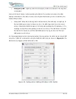
For those applications where prolonging battery life is essential, the LEDs can be turned OFF 

using the ^LEDS AT command or using the SatTerm LED’s tab, as shown in 

Figure 16

The 

9602-LPs are shipped with all LEDs set to ON. 


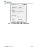
Figure 16. Configuration Settings Window: LED’s Option 

Summary of Contents for 9602-LP

Page 1: ...yright 2020 by NAL Research Corporation 11100 Endeavor Ct Suite 300 Manassas Virginia 20109 USA Phone 703 392 1136 Email contact nalresearch com 9602 LP User Guide Version A April 20 2022 451 92750 00...

Page 2: ...e use or related to the performance or nonperformance of any products accessories facilities or services or information except as expressly stated in this guide and or the Product and or satellite ser...

Page 3: ...9602 LP User Guide Version A Document Number 451 92750 001A 3 of 61 REVISION HISTORY Revision Date Description 1 4 6 04 05 2021 Initial version A 03 28 2022 Formal release updated to new template...

Page 4: ...01A 4 of 61 REFERENCE DOCUMENTS The latest revisions of the NAL documents are available from the NAL Research website at https www nalresearch com support documentation downloads Reference Title Revis...

Page 5: ...Emergency and Test Tracking Modes 24 3 2 Encryption Setting 25 3 3 Miscellaneous Settings 26 3 4 LED Settings 27 3 5 Tracking Settings 29 3 6 GPS Settings 31 4 Motion Sensor 32 5 Iridium Antenna Conne...

Page 6: ...g Mode Settings 20 Figure 9 Normal Tracking Callable Yes Option 21 Figure 10 Normal Tracking Callable No Option 22 Figure 11 Normal Tracking Awake on Motion 23 Figure 12 Normal Tracking Callable Movin...

Page 7: ...ure 32 Average Current During GPS Acquisition 6 VDC to 32 VDC Input 43 Figure 33 Average Power Consumption During GPS Acquisition 3 5 VDC to 32 VDC Input 43 Figure 34 Average Current during SBD 3 VDC...

Page 8: ...nt of Defense DSN Defense Switch Network DTE Data Terminal Equipment EAR Export Administration Regulations EGNOS European Geostationary Navigation Overlay Service EMI Electromagnetic EMSS Enhanced Mob...

Page 9: ...ge structure PPP Point to Point Protocol PSTN Public Switched Telephone Network PWR Power RF Radio Frequency RHCP Right Handed Circular Polarization RUDICS Router based Unrestricted Digital Internetwo...

Page 10: ...o be used to track environmentally demanding platforms including helicopters fixed wing aircraft unmanned aerial vehicles rockets high altitude balloons ships speedboats ground vehicles and remote una...

Page 11: ...visioned Unauthorized attempts to access the DoD EMSS gateway result in immediate disabling of the offending device which must then be returned to NAL Research for repair See https sbd pac disa mil fo...

Page 12: ...wire RS232 serial data interface TTL CMOS I Os Reserved RS232 serial data interface Table 1 Pin Assignments for the 9602 LP Multi Interface Connector Pin Signal Description Interface 1 EXT_PWR Extern...

Page 13: ...be changed to 6 0 VDC to 32 VDC input through an internal jumper POWER MUST BE DISCONNECTED BEFORE RESETTING THE JUMPER To set the voltage input range Remove the modem s top plate to find the jumper W...

Page 14: ...The HRC 24 12 has a three foot RS 232 cable for connection onto a computer and three wires for DC power inputs to a 9602 LP Model HRC 24 12 is available on the NAL website www nalresearch com Figure...

Page 15: ...s under the I O tab of the Configuration Settings window as shown in Figure 5 The four CMOS TTL inputs denoted as S0 through S3 have internal pull ups which allow the inputs to float as high The input...

Page 16: ...guration you can trigger Emergency Tracking at any time with a quick press and release of the Emergency button momentary switch o Once enabled holding the emergency button longer than three seconds ta...

Page 17: ...nd specifies the type of emergency switch as either momentary default or latching similar to the toggle switch on the 9601 DGS LP o The momentary switch type functions as described above o When set to...

Page 18: ...on use the AT TRK command to switch from Command mode to Tracking mode switch from Tracking mode back to Command mode with the escape sequence The flow chart in Figure 7 describes operating modes of t...

Page 19: ...of unique settings as shown in Figure 8 Each setting can be tailored to meet specific applications For example the 9602 LP can be preprogrammed to transmit reports at fixed intervals to transmit repo...

Page 20: ...rising edge or a falling edge of a TTL CMOS input signal is detected Once the last GPS report is sent the 9602 LP goes back to Normal Tracking The Same Place Skip Reports option prevents GPS reports f...

Page 21: ...he motion sensor The 9602 LP draws the lowest current in between reports of around 60 A at 5 VDC The 9602 LP will not respond to any entered commands including the The command works only while the tra...

Page 22: ...9602 LP s micro controller When at rest it normally settles in a closed state Three parameters must be provided when choosing the Awake on Motion option Minutes of Motion Before Waking Sensitivity and...

Page 23: ...between the Callable Yes and Callable No configurations When in motion the 9602 LP uses a set of Callable Yes parameters to send GPS reports when not in motion the 9602 LP uses a set of Callable No p...

Page 24: ...k to Not in Motion or Low Power mode Figure 12 Normal Tracking Callable Moving Yes Still No Option 3 1 2 2 EMERGENCY AND TEST TRACKING MODES Emergency Tracking can be triggered by the Emergency button...

Page 25: ...saved into the 9602 LP This default password must be changed before any encryption properties can be set or changed To change the default password 1 Click Change to open the Change Crypto Officer Pass...

Page 26: ...ous Options Use Remote Update Password to set the required password when a remote update to the current active operating profile is made from a command center while the 9602 LP is in the field The pas...

Page 27: ...Tracking mode Power LED Lights up when power is applied to the 9602 LP and power on button is pressed GPS LED Stays solid when there is a valid GPS position fix blinks when there is 2 D fix or when us...

Page 28: ...the last SBD session does not have an error the LED stays solid An error occurs when a transmitted SBD message is not being acknowledged by the gateway or if a message received from the gateway conta...

Page 29: ...center GPS Always ON forces the GPS receiver to stay on in between reports allowing hot start each time the 9602 LP wakes up Start Up Mode sets the power up mode of the 9602 LP The 9602 LP allows GPS...

Page 30: ...9602 LP User Guide Version A Document Number 451 92750 001A 30 of 61 Figure 17 Configuration Settings Window Tracking Options...

Page 31: ...on Setting window the GPS option allows you to obtain GPS information from the 9602 LP serial port while the unit is in Command mode or Tracking mode similar to the command PG Both GPS NMEA formats an...

Page 32: ...fed directly into the 9602 LP s microcontroller to wake up the 9602 LP out of sleep mode when activity is sensed and to transmit location report The 9602 LP s motion sensor can be enabled or disabled...

Page 33: ...ting frequency of 1616 to 1626 5 MHz NAL Research offers several types of antennas for use with the 9602 LP These antennas include the fixed mast mobile magnetic permanent mount and portable auxiliary...

Page 34: ...dium Antenna s Design Specifications Parameter Value Return Loss Minimum 9 5 dB Gain 0 0 dBic weighted average minimum VSWR 1 5 1 Minimum Horizon Gain 2 0 dBic 82 conic average Nominal Impedance 50 Oh...

Page 35: ...enna as well as dual Iridium GPS antennas for use with the 9602 LP For low cost and applications where small form factor and light weight are required NAL Research highly recommends model SAF7352 IG a...

Page 36: ...ntenna rather than disconnect and reconnect the antenna Important Never feed external supply voltage into the active GPS antenna Always use the bias voltage supplied by the 9602 LP via the SMA antenna...

Page 37: ...e of sight is not available between the 9602 LP and satellite 2 The higher the antenna Voltage Standing Wave Ratio VSWR the higher the current consumed 3 And manufacturing variation from device to dev...

Page 38: ...ent is measured when all circuits are on The average current drawn during standby with 3 6 VDC 5 VDC input and 6 VDC 32 VDC are shown in Figure 24 and Figure 25 respectively Figure 24 Average Current...

Page 39: ...tion During Standby 3 5 VDC to 32 VDC Input In tracking mode the 9602 LP goes through three different power consumption segments 1 The sleep in between reports segment 2 GPS acquisition segment and 3...

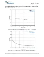
Page 40: ...cking Mode The average current drawn by the 9602 LP during sleep with 3 6 VDC 5 VDC input is shown in Figure 28 Figure 28 Average Current During Sleep 3 5 VDC to 5 VDC Input 220 240 260 280 300 320 Ti...

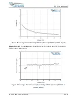
Page 41: ...re 29 Due to limitations of our signal analyzer current drawn for voltages above 15 VDC in the A range could not be measured The dashed line results from curve fitting cubic spline of the data Figure...

Page 42: ...DC Input During the GPS acquisition segment the average current drawn by the 9602 LP with 3 6 VDC 5 VDC input and 6 VDC 32 VDC are shown in Figure 31 and Figure 32 respectively The GPS acquisition tim...

Page 43: ...Figure 32 Average Current During GPS Acquisition 6 VDC to 32 VDC Input Figure 33 shows the average power consumption by the 9602 LP during GPS acquisition for the entire voltage range Figure 33 Avera...

Page 44: ...he SBD transmission segment the average current drawn by the 9602 LP with 3 6 VDC 5 VDC input and 6 VDC 32 VDC are shown in Figure 34 and Figure 35 respectively Figure 34 Average Current during SBD 3...

Page 45: ...p to attain the lowest possible power consumption Some setup parameters to be carefully observed include Have a clear view of the sky for both the GPS and Iridium antennas poor visibility of the sky i...

Page 46: ...9602 LP User Guide Version A Document Number 451 92750 001A 46 of 61 8 LIST OF KNOWN ISSUES None...

Page 47: ...9 TECHNICAL SUPPORT For technical support please contact us at Phone 703 392 1136 Ext 200 or Email contact nalresearch com Technical documents are also available to download on NAL Research s website...

Page 48: ...to the regulatory and technical certifications shown in Table 3 Table 3 Standards Compliance Regulatory Approvals Radio Tests EMC Tests Mechanical Electrical Tests CE ETSI EN 301 441 V1 1 1 2000 05 E...

Page 49: ...ilure to comply can result in the imposition of fines and penalties the loss of export privileges and termination of your contractual agreements with NAL Research The export and re export of NAL Resea...

Page 50: ...n provide truly real time and global coverage from pole to pole Figure 37 Iridium Network The Iridium network is designed to operate in the band of 1616 to 1626 5 MHz although the exact frequencies us...

Page 51: ...e satellite constellation provides connectivity between users from a user to the Iridium system gateway and between gateways Within the Iridium network architecture the satellites are cross linked whi...

Page 52: ...em training can range from 15 to 30 seconds For an Iridium to Iridium call dial up data service offers an additional option known as Data After Voice DAV Similar to a voice call a DAV call is routed d...

Page 53: ...a connection with the Iridium gateway through the Iridium satellite constellation Because the Iridium modem is requesting to establish a data connection the switch at the gateway routes the call throu...

Page 54: ...led telephone number is an international number provided by Iridium Figure 40 illustrates how an Iridium internet call is routed Direct Internet service can be enhanced using Windows based emulated Po...

Page 55: ...a messages over the Iridium satellite network to the NIPRNet internet Iridium SMS service incorporates a subset of the Global System for Mobile Communications GSM SMS features Each SMS message can be...

Page 56: ...eolocation of an ISU each time a call is placed The technique employed to determine the geolocation of an ISU is based on measurements of the ISU and satellite propagation delay and Doppler frequency...

Page 57: ...dium Antenna SMA female GPS Antenna SMA female OFF ON Switch Push Button Emergency Switch Guarded Button and or External via Multi Interface Connector Status LED Displays Power GPS Iridium SBD status...

Page 58: ...unt voltage drop across the power supply cable to ensure adequate current provided to the 9602 LP during SBD sessions If input voltage does not stay above 3 0 VDC during surge or high current demand t...

Page 59: ...st Data Mobile Terminated 270 bytes per message Hardware Interface 3 Wire RS232 Software Interface AT commands RELATED HARDWARE Antennas SYN7391 Series SAF2040 Series SAF5340 Series SAF5350 Series SAF...

Page 60: ...s Cold starts 28 seconds Sensitivity Tracking 160 dBm Reacquisition 160 dBm Cold starts 147 dBm Operational Limits COCOM restrictions apply Altitude 164 000 feet 50 000 meters Velocity 1 640 feet sec...

Page 61: ...9602 LP User Guide Version A Document Number TN2021 001 V A 61 of 61 APPENDIX F MECHANICAL DRAWINGS Figure 41 9602 LP Mechanical Drawing...

Reviews: