12
DT Series - Installation manual (V4_2022)
3.
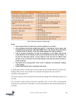
SPECIFICATIONS
MODEL
INPUT CAPACITY
NET OUTPUT CAPACITY
TURNDOWN RATIO
AIRFLOW
CFM
L/S
MBTU
KW
MBTU
KW
MIN
MAX
MIN
MAX
55
688
200
550
160
10:1
4244
10185
2003
4808
65
813
237
650
189
10:1
5015
12037
2368
5682
75
938
273
750
219
10:1
5787
13889
2732
6556
85
1063
310
850
248
12:1
6559
15741
3096
7430
100
1250
364
1000
291
12:1
7716
18519
3642
8742
125
1563
455
1250
364
12:1
9645
23148
4553
10927
150
1875
546
1500
437
12:1
11574
27778
5464
13112
175
2188
638
1750
510
17:1
13503
32407
6374
15298
200
2500
729
2000
583
18:1
15432
37037
7285
17483
250
3125
911
2500
729
15:1
19290
46296
9106
21854
300
3750
1093
3000
874
15:1
23148
55556
10927
26225
350
4375
1275
3500
1020
18:1
27006
64815
12748
30596
400
5000
1457
4000
1166
20:1
30864
74074
14569
34966
500
6250
1821
5000
1457
20:1
38580
92593
18212
43708
Table 2: General specifications
NOTES:
•
Net output capacities are based on 80% combustion efficiency for natural gas, some
models may have higher efficiency
•
Airflow is intended for temperature rise of 50°F to 120°F (28°C to 67°C)
•
1 MBTU: 1000 BTU/ Hr
•
CFM: Cubic foot per minute
•
Ratings are based on 1000 Btu/ft
3
for natural gas at sea level
•
Reduce burner capacity for altitude over 2000ft by 4% for each 1000ft above sea level
•
Consult factory for turndown ratio for propane gas


