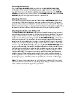
4
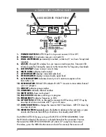
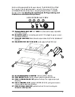
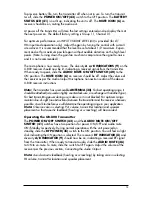
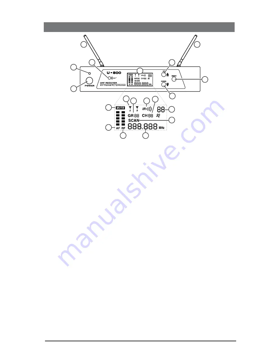
1. POWER BUTTON bUTTON push in to power receiver ON or OFF
2. POWER LED LED indicates receiver is turned ON
3. DUAL ANTENNAS permanently mounted., rotate to 45° as shown for optimal
reception
4. ASC/IR infrared LED window for sync receiver and transmitter. Transmits LED
Infrared signal for linking the receiver to the transmitter for frequency downloads
5. LCD DISPLAY shows receiver current status
6. MUTE ICON indicates audio muted
7. AF INDICATOR displays received Audio level
8. RF INDICATOR displays received radio signal level
9. A/B INDICATORS indicates diversity A or b antenna reception when
transmitter is on
10. IR INDICATOR INDICATOR indicates IR ASC™ receiver-to-transmitter channel
sync is in progress
11. GROUP indicates group number
12. CHANNEL indicates channel number
13. MUTE LEVEL shows muting level
14. SCAN ICON indicates scanning is in progress
15. FREQUENCY indicates frequency in MHz
16. UP BUTTON bUTTON to change the receiver MUTE level up, GRp/CH up by
one step at a time or activate ASC™ sync in IR menu
17. DOWN BUTTON to change the receiver MUTE level down, GRp/CH down by
one step at a time
18. MENU BUTTON repeatedly press the button to advance to the next menu, or press
once to start the Auto Scan/IR/Sync function or to manually select GR/CH
Use MENU bUTTON for easy set up with ONE TOUCH pROGRAMMING. Start
the IR link download of the receiver’s selected channel to the transmitter. position
the transmitter IR RECEPTOR WINDOW (37,44) 6-12” away from the receiver
IR window, press the MENU button once and wait five second, the receiver will
4. QUICk USER CONTROLS GUIDE
U-800 RECEIVER: FRONT VIEW
1
2
3
4
5
16
3
18
17
11
10 12
14
15
13
9
6
7
8

