check the level of the electrolyte and, if necessary, top off with
distilled water.
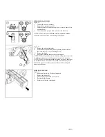
LEVEL INDICATOR FOR THE CHARGE OF
THEBATTERIES
Figure 9
The batteries’ indicator is digital with 4 fixed positions and a blinking
one. The numbers which appear on the display show the approximate
charge level.4 = maximum charge, 3 = charge 3/4,2 = charge 2/4, 1
= charge 1/4,0 = (blinking) discharged batteries .
ATTENTION: A few seconds after the meter reads “0” it will start
blinking; the brush motor will then automatically switch off. Anyway,
the machine can finish to dry before recharging the batteries.
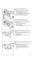
SQUEEGEE
Figure 10
The squeegee, which is packed separately from the machine, should
be installed onto the machine as shown in the figure. Insert the stud
bolts on the squeegee (1) into the proper slotted hole in the support
frame. Install the hair pin (2) into the stud bolthole. Fit the suction
hose (3) into its coupling and fix it with the appropriate clamp.
Figure 11
During operation, the rear rubber has to work slightly tilted
backwards and this equally in its whole length for about 5 mm. This
allows using the squeegee four times before it has to be replaced.
Figure 12
If it is necessary to increase the rubber bending in the central part, tilt
the squeegee body backwards, loosen the adjuster nut (1) and rotate
the knob (2) counter-clockwise. If the rubber bending is to be
noticeable at the sides of the squeegee, loosen the adjuster nut (1) and
rotate the knob (2) clockwise. After regulations have been done fix
the adjuster nut.
- 5 -


