background image


ADJUSTMENT SPLASH GUARDSWASHING/SCRUBBING


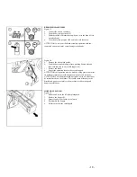
BASE (brooms) 
Figure 60 
Periodically proceed with the height adjustment of the side 
splashguards of the base. This operation has to be carried out with the 
base down. 
1. 

Loosen the fixing lock nut of the support bars (1). 

2. 

Regulate the splashguards with the screw (2). 

3. 

Block the lock nut (1). Keep in mind that the rubber must skim 
the floor and be parallel to it. 


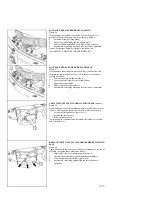
CLEANING OF THE SUCTION HOSE 

Figure 61 
Whenever suction seems to be unsatisfactory, check that the suction 
hose is not obstructed. Eventually, clean it with a water jet introduced 
from the side where it is being connected to the tank. Proceed as 
follows: 
1. 

Loosen the clamp, which tightens the hose. 


Figure 622.  
2. 

Clean with a water jet introduced from the side where it is 
connected to the tank. 

3. 

Reassemble everything proceeding inversely with above 
operations. 

ATTENTION: this operation must be made by using gloves to protect 
from the possible contact with dangerous materials and solutions. 


- 20 - 

Summary of Contents for ST900 SERIES

Page 1: ...OWNERS MANUAL ST900 SERIES 1205 Britannia Road East Mississauga ON L4W 1C7 Phone 1 800 387 3210 Fax 1 800 709 2896 ...

Page 2: ...achine which using the mechanic abrasive action of two rotary brushes and the chemical action of a water detergent solution is able to clean any type of floor During its advance movement it picks up the removed dirt and the detergent solution which has not been absorbed by the floor The machine must be used only for such purpose We would impress upon you that any machine will function efficiently ...

Page 3: ...is used to indicate the switch to raise or lower the squeegee Symbol denoting regulation cock Symbol denoting the horn button Symbol denoting the MAIN POWER on off switch Symbol denoting the forward reverse switch According to its position the machine moves forward or backward Symbol denoting maximum temperature of the cleaning solution to be used Symbol denoting the drain hose of the recovery tan...

Page 4: ...machine down from the pallet pushing it in reverse motion Avoid violent blows to the baseunit 5 Keep the pallet for future transport necessities INSTALLATION OF THE BATTERIES INTO THE MACHINE Figure 4 The batteries are fitted in the appropriate compartment under the seat and under the recovery tank and must be handled by using appropriate lifting equipment suitable both for the weight and for the ...

Page 5: ...le instructions see instruction booklet of the battery charger ATTENTION this operation must be carried out by specialized staff A wrong or defective connection of the cables to the connector may cause serious damages to people or things RECHARGE OF THE BATTERIES Figure 8 Make sure that the battery charger fits the installed batteries either for capacity or for type lead acid or GEL and equivalent...

Page 6: ... should be installed onto the machine as shown in the figure Insert the stud bolts on the squeegee 1 into the proper slotted hole in the support frame Install the hair pin 2 into the stud bolthole Fit the suction hose 3 into its coupling and fix it with the appropriate clamp Figure 11 During operation the rear rubber has to work slightly tilted backwards and this equally in its whole length for ab...

Page 7: ...for aggressive scrubbing cleaning and stripping by increasing pressure 2 Washing sweeping unit with cylindrical brooms Suitable for rough uneven and grouted surfaces Will scrub and sweep debris in one pass and collect the solid debris into a hopper without obstructing the squeegee rubbers WASHING UNIT ASSEMBLY brushes Figure 15 1 Loosen the knobs 1 from the horizontal pins on the left side of the ...

Page 8: ...upling of the right brush The left brush has to be rotated inversely ATTENTION use gloves to protect your hands when performing the steps listed above Figure 19 6 It is recommended to invert daily the position of the right brush with the left one and vice versa If the brushes are not new and they show deformed bristles its better to reassemble them in the same position the right to the right side ...

Page 9: ... hub keeping the v shaping as in the picture 8 Insert the idle hub of the movable support into the brooms and into the spring 9 Push the support downwards and then inwards to refasten in the bayonet cap 10 Regulate the brushes adjustment with the screw 2 11 Repeat the operation also for the second support 12 Reassemble the side splash guards see ASSEMBLY AND DISASSEMBLY OR REGULATIONSIDE SPLASH GU...

Page 10: ...d damage the suction motor so use only the minimum amount of detergent necessary ATTENTION Always use low foam detergent To avoid the production of foam before starting to clean put a minimum quantity of antifoam liquid into the recovery tank Never use pure acid RECOVERY TANK Figure 26 Check that the inspection cover has been tightened Figure 27 And that the exhaust plug of the tank Figure 28 And ...

Page 11: ...scaffoldings where there is danger of falling objects Adapt the utilization speed to the adhesion conditions Do not exceed the declared hill climbing capacity otherwise the machine could become unstable When the machine is in parking position take off the key and insert the parking brake The machine has to carry out simultaneously the operations of washing and drying Different operations have to b...

Page 12: ... turn Immediately the battery display 3 and the hour meter 4 switch on Figure 30 5 Position the switch of the squeegee up down 1 into position down the suction motor works 6 Push the switch of the brushes base up down 2 into position down till you reach the stroke end The brushes will start rotating only by operating the accelerator pedal Figure 31 7 Collocate forward the drive selector 1 Figure 3...

Page 13: ...immediately apply the emergency brake by 1 Depressing brake pedal and moving foot pedal backwards to lock at the same time 2 Turn the key counter clockwise to the OFF position To re start after resolving the problem turn the key clockwise and release the emergency parking brake by depressing and pushing the pedal forward Figure 35 The machine will not start if the operator is not properly seated R...

Page 14: ...pedal similar to an automobile regulates the machine speed Figure 37 NOTE During reverse motion the squeegee raises automatically and the water supply stops automatically BRAKES Figure 38 The machine is equipped with an electronic braking system To brake in normal conditions it is sufficient to take the foot off the movement pedal Figure 39 In case of bad operation of this brake or in case of nece...

Page 15: ...orn activated by the button on the instrument control panel In reverse the horn works automatically BLINKING LIGHT Figure 41 The machine is equipped with a blinking light that turns on automatically when you turn the key switch to the ON position 14 ...

Page 16: ... recommended to hold the hose bent with one hand and with the other unscrew the knob and take off the plug Slowly straighten the hose and the liquid will start draining at the desired speed This operation has to be carried out using gloves to protect from contact with dangerous solutions ATTENTION This operation must be made by using gloves to protect from the contact with dangerous solutions 7 Th...

Page 17: ...EANING OF THE SQUEEGEE Clean the squeegee with a water jet Check the rubber wear and if necessary turn them upside down or change them The careful cleaning of the complete suction group assures higher life of the suction motor REPLACEMENT OF THE SQUEEGEE RUBBER Figure 48 If the squeegee rubber is worn and does not dry well it is possible to change the drying edge proceeding as follows 1 Push and r...

Page 18: ...o position OFF and take it off the board ATTENTION to carry out the brush assembly operation with the connected current on it may cause damage to the hands Figure 52 5 Rotate the brush so that it comes out the seat of the brushes holder plate as indicated in the picture In the picture the rotation direction for the right brush release is indicated for the left one rotate in reverse direction ATTEN...

Page 19: ... outwards the two movable supports 1 7 Remove the brush 8 Repeat the operation also for the second support ATTENTION this operation must be made by using gloves to protect from the possible contact with dangerous materials and solutions ATTENTION The cylindrical brush unit when not in use should not be stored directly on the brushes This could cause deformity to the bristles and upon re assembly t...

Page 20: ... block the front rubber 3 Slip off the rubber blade 4 Slip off the rubber and replace it 5 Reassemble everything repeating inversely above operations ADJUSTMENT SPLASH GUARD WASHINGBASE brushes Figure 58 Periodically proceed with the height adjustment of the side covers of the base This operation has to be carried out with the base down 1 Loosen the fixing knobs of the covers 1 2 Position the cove...

Page 21: ...o it CLEANING OF THE SUCTION HOSE Figure 61 Whenever suction seems to be unsatisfactory check that the suction hose is not obstructed Eventually clean it with a water jet introduced from the side where it is being connected to the tank Proceed as follows 1 Loosen the clamp which tightens the hose Figure 622 2 Clean with a water jet introduced from the side where it is connected to the tank 3 Reass...

Page 22: ...HES DISASSEMBLY or BRUSHES ASSEMBLY 2 Use a different kind of brushes to the ones fitted as standard For cleaning operations on floors where the dirt proves to be particularly resistant we recommend using special brushes which may be supplied optionally according to needs see under CHOICE AND USE OFBRUSHES 3 THE SQUEEGEE DOES NOT DRY PERFECTLY 1 Check that the squeegee is clean 2 Adjust the height...

Page 23: ...are properly connected 5 Check that the batteries are fully charged by the battery indicator 6 Check that no thermal protection is activated See THERMAL PROTECTORS THE BRUSHES MOTOR DOES NOT WORK Figure 67 ATTENTION To avoid damage to the floor the motor starts only when the machine goes forward 1 Check that the base is down 2 Check that the batteries are fully charged 3 Verify the electrical conn...

Page 24: ... is generated In this case dilute more the detergent THERMAL PROTECTORS Circuit Breakers Figure 68 There is a thermal protections system for the following functions 1 Base up down actuator 2 Solenoid valve and water pump 4 General protection 5 Squeegee up down actuator 6 Traction In case of block of the specific function put back in operation the functioning pushing the proper button near the symb...

Page 25: ...e toughest scale THICKNESS OF THE BRISTLES The thicker the bristles are the more rigid they will be These ones are therefore used on smooth floors or with small joints On uneven floors with deep joints it is recommended that softer bristles which enter more easily in depth be used Please bear in mind that when the bristles are worn out and get too short they will get rigid and cannot penetrate any...

Reviews: