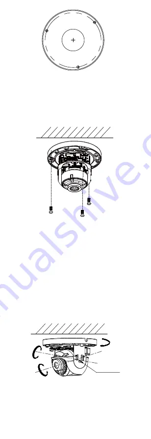
Figure 2-1
Drill Template
Note:
Drill the cable hol
e if planning to route the cable
through the ceiling/wall.
Note:
The supplied screw package contains self-tapping
screws, and
plastic anchors
.
For cement wall/ceiling,
plastic anchors
are
required to
mount
the camera. For wooden
wall/ceiling, self-tapping screws are required.
Drill Template
Hole A: for cables routed through the ceiling
screw hole 1: for Mounting Base
1
1
1
A
3.
Route the cables and fix the mounting base on
the ceiling with
three screws.
Figure 2-
2
Fix the Mounting Base
4.
Adjust
the camera viewing angle (aim).
1).
Loosen one adjust
ment
screw to adjust the tilt
position. Tighten the screw after adjustment.
2).
Hold the black liner to adjust the panning position.
3).
Hold the
black liner and turn the lens to adjust the rotation.
Tilting Adjust
Screw
Pan:
0° to 355°
Tilt:
0° to 75°
Rotate: 0° to 355°
Figure 2-3
Adjust Viewing Angle


