background image


26 of 34


GT20 8300-8350 Overhead Concealed Operator Installation Manual 

www.NabcoEntrances.com

P/N C-00183 

Rev 8-31-16

SECTION 13 .2 FSLAM POTENTIOMETER (POWER OFF)

• Only adjust the Cam when absolutely necessary . 
• During a Power Failure or when Power is turned OFF, ONLY adjust the Cam if the FSlam 

Potentiometer will not close the Door after repeated adjustment attempts have been made . 

The Cam can be adjusted to vary the angle where the slam function will start .

Note:  The FSlam Potentiometer is utilized for Standard Application only (not Inverse Application).

When Power is OFF or during Manual Mode, the Motor slows the Door Panel down to a constant closing speed until the Full Closed 

position is reached and the Door Panel is locked. This is done  by utilizing the FSlam potentiometer (accelerated force). To ensure the 

FSlam parameter setting  is correct:

1. Open the door Panel 90 degrees, then let it go.

a.  If the Door Panel fails to fully close and then lock, adjustments are deemed necessary.

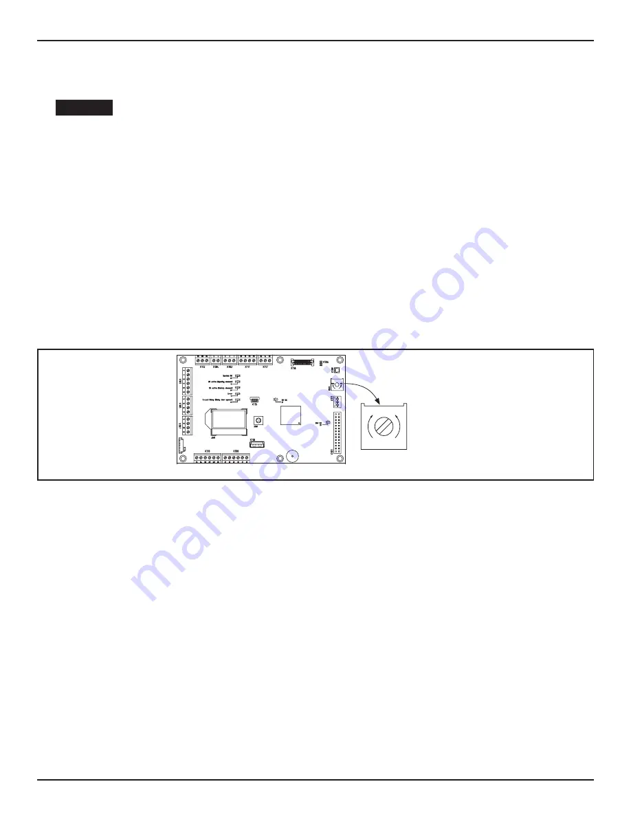
1.►Go to the GT20 Control.
2.►Go to either side of the GT20 Control to locate a Blue square.

a.  Exact location Depends upon the type of installation.

3.►With a flat head screwdriver turn the Potentiometer:


X

Clockwise for maximum accelerated force.


X

Counterclockwise for minimum accelerated force.

DN 1175

FSlam Poten ometer

Adjuster

max. min.

Figure 42 Adjust Closing Force

SECTION 13 .3 Adjust the Activation Angle

Note: By default, the FSlam Angle (from the Fully Closed Position) is approximately 5 degrees.

1. Carefully pry the Service Cover from the gearbox housing with a flathead screwdriver.
2. Locate the Cam Disk. 

a.  The Locking Screw may be positioned under Cam Setting 1 or Cam Setting 2.

3. Slightly loosen the Locking Screw with a 1.5mm socket wrench. 
4. According to Table 8, turn the Cam Disk clockwise or counterclockwise to adjust the Angle. 

a.  Angle range is between 5 degrees - 15 degrees.

5. Tighten the Locking Screw.
6. Open the Door Panel 45 degrees, then let it go. 


X

If the Door Panel locks:

•► Snap the Service Cover back onto the Gearbox Housing.


X

If the Door Panel fails to lock:

•► Repeat steps 1 - 5 accordingly.

CAUTION

Summary of Contents for GT20 8300

Page 1: ...ECTION 5 1 Prep the Jamb Tubes 10 SECTION 5 2 Install the Header to Jamb Tubes 10 SECTION 5 3 Install the Frame to Building 11 SECTION 5 4 Install the Fingerguard 12 SECTION 5 5 Install the Floor Pivo...

Page 2: ...ure the Arm to the Operator 22 SECTION 9 2 Secure the Swing Arm to the Swing Door 22 CHAPTER 10 120 VAC GENERAL WIRING 23 CHAPTER 11 THE MOTOR CONNECTOR HARNESS 23 SECTION 11 1 Determine the Spindle R...

Page 3: ...able surfaces Do not place finger or uninsulated tools inside the electrical controller Touching wires or other parts inside the enclosure may cause electrical shock serious injury or death Read this...

Page 4: ...to familiarize the installer and purchaser with the proper installation and operation of this system It is essential that this equipment be properly installed and operational before the door is used...

Page 5: ...Motor Voltage 30V Motor Power Rating 100 W Power consumption Max 560 W Maximum Door Weight Full Energy 550 pounds 250 kg Low Energy 220 pounds 100 kg Minimum Height of Door Panel 6 Feet 1 83m Width of...

Page 6: ...by a 2 Operator Assemblies Low Energy Utilize a Knowing Act to open a Swing door Full Energy Utilize Sensor s to open a Swing door Air Lock w optional plug in board Activation of first Door Panel pre...

Page 7: ...a 3 1 m p h 5 0 k m h 1 2 5 P a 2 7 m p h 4 5 k m h 1 0 0 P a 2 4 m p h 4 0 k m h 8 0 P a 2 1 m p h 3 5 k m h 6 0 P a 9 8 3000mm 9 5 2900mm 9 2 2800mm 8 8 2700mm 8 5 2600mm 8 2 2500mm 8 2400mm 7 6 23...

Page 8: ...verse Swing Door An internal spring located inside the Operator automatically OPENS the Swing door unless the Swing door has been locked with a Fail Secure electric lock An internal Brake located insi...

Page 9: ...Determine GT 20 Operator Handing 4 7 2 Determine Handing from Direction the OHC Swing Door Opens If the Swing Arm swings underneath the Threshold to open it is an Outswing Unit If the Swing Arm does...

Page 10: ...diameter holes through 4 clearly marked A s on the Template Countersink each screw hole 6 Obtain 4 Rivnuts provided by NABCO Install 1 Rivnut into each drilled 391 hole 7 Drill 1 1 1 4 inch diameter h...

Page 11: ...h opening Insert all incoming wiring through the 1 1 4 inch hole located on side of Header 2 Plumb Jamb tubes in both planes to ensure the rough opening allows a 1 4 inch clearance Shim back of Jamb a...

Page 12: ...Weather Strip onto Finger Guard Mounting Plate DN 0470 Weather Strip Channels Weather Strip Channels Finger Guard Moun ng Plate SIDE VIEW Assembled Finger Guard 4 Line up the Center Notch located down...

Page 13: ...ter of the Pivot Jamb and the Floor Pivot 3 Butt the center mark of the Floor Pivot up against the center mark of the Pivot Jamb 4 Align both Pivot Shafts Drop a Plumb Line down the center from the To...

Page 14: ...e Threshold to the Strike Jamb 4 Obtain 10 x 1 1 2 inch sheet metal screws and anchors per length of the Saddle Threshold 5 In the center of the Saddle Threshold approximately 4 inches from the cutout...

Page 15: ...Screw Self Riser Screw Bo om side of Top Pivot Assembly Top Pivot Assembly Figure 20 The Center Pivot Shaft 3 Go to the bottom Pivot Assembly Insert the Ball Bearing onto the Floor Pivot Shaft Figure...

Page 16: ...either side of the track to insure proper centering of the track in the door web These side spacers may be le in the door or be removed a er the track is securely in place Use the 1 4 20 rivnuts for a...

Page 17: ...ith a Q drill 332 dia through 1 wall and countersink to 53 dia x 82 Remove material as needed NOTES For other Door Rail requirements not shown contact customer service at 1 877 622 2694 Prepare Swing...

Page 18: ...ger Guard 3 5 8 inches X X Without the Finger Guard 2 5 8 inches 4 Mark a vertical line across the horizontal line onto the Web face This is the center of the Bearing 5 From the center of the Bearing...

Page 19: ...t 3 8 inch Spacer Block X X 1 9 16 inch deep Insert 2 3 8 inch Spacer Blocks 8 Place 1 Track on top of the Spacer Block or the Web if a Spacer Block is not used a Ensure the Pivot Pin Receiver is on t...

Page 20: ...until the Pivot Shaft is inserted all the way down into the Bearing 7 Slide the Track Assembly back and forth until the Swing door is properly aligned a It is recommended to use a Level 8 Tighten the...

Page 21: ...e center of the Saddle Threshold approximately 4 inches from the Strike Jamb mark 1 screw hole Figure 32 Mark and Drill Holes on Saddle Track DN 0752 Strike Jamb 1 4 Screw Holes Cut Out for Pivot Plat...

Page 22: ...letely released by means of the Adjusting Screw 3 Secure the Swing Arm to the Operator with 1 Bolt Figure 36 Secure the Swing Arm to the Operator DN 1281 Spindle Extension Swing Arm Output Sha Bolt 15...

Page 23: ...at the left or right side of Header End Cap Note It is recommended for the Installer to house all Incoming 120 VAC wires within an Electrical Conduit Note For detailed wiring please refer to the GT20...

Page 24: ...rammed the door can burst open unexpectedly during TEACH Please refer to Table 6 as a guide to select the appropriate Unit for each Male Connector Table 6 Handing and Spindle Rotation Male Connector O...

Page 25: ...f it butts up against the side cover where the Power Mode Switch is installed X X Pre load adjustments must be done before carrying out the automatic set up procedure X X Adjust the spring pressure so...

Page 26: ...adjustments are deemed necessary 1 Go to the GT20 Control 2 Go to either side of the GT20 Control to locate a Blue square a Exact location Depends upon the type of installation 3 With a flat head scr...

Page 27: ...on could be reversed MOTOR Figure 43 Adjust Activation Angle Table 8 Angle Range Angle Range according to Cam Setting Setting Swing Arm Mount Angle Range 1 Inswing Arm pull Frame Smaller Outswing Arm...

Page 28: ...VER Open Close the Swing Door OHC Track for 7 8 inch Web 21 3561 Item Part QTY Description Used To 1 A 00500 1 BTTM PIVOT ASSY DOOR PORTION SWING DR Open Close the Swing Door 2 A 00459 1 PIVOT BLOCK O...

Page 29: ...rack within Top Rail 6 M 01342 2 BLOCK SPACER 3 8 Adjust height of Track within Top Rail OHC Track for 1 inch Web 21 0928 Item Part QTY Description Used To 1 A 00500 1 BTTM PIVOT ASSY DOOR PORTION SWI...

Page 30: ...ealed Operator Installation Manual www NabcoEntrances com P N C 00183 Rev 8 31 16 Night Exit Hold Open Manual DN 1512 Service Parts GT20 OHC HEADER 1 2 3 4 5 6 7 8 9 10 11 12 13 14 15 16 17 18 19 23 2...

Page 31: ...16 DRIVE MODULE GT20 14 V 00326 Optional BOARD RELAY GT20 15 M 01740 CABLE ENCODER GT20 OHC 16 M 01739 HARNESS POWER GT20 OHC 17 M 01741 CABLE SWITCH GT20 OHC 18 V 00420 SWITCH JAMB GT20 19 T 00337 PH...

Page 32: ...ntrances com P N C 00183 Rev 8 31 16 DN 1515 Service Parts OHC SWING DOOR VIEWED FROM BREAK OUT SIDE 1 2 3 4 5 6 7 8 9 10 11 12 13 14 15 16 17 18 19 20 24 23 22 21 25 26 27 28 29 30 31 33 34 35 37 36...

Page 33: ...MUNTIN 261 HOLE 18 T 00061 FHMS 1 4 20x1 000L PHIL TRI LOBE ZINC 19 A 00500 BTTM PIVOT ASSY DOOR PORTION SWING DR 20 M 01053 SPACER BASE PIVOT OHC 21 A 00610 PIVOT BASE OHC 22 T 00172 FHMS 1 4 20x2 00...

Page 34: ...E A 70012 BLOCK PILLOW MACH 43 T 00031 FHMS 10 32x0 500L PHIL UCUT T LOBE BKZN 44 24 5475 01 Clear PUSH BAR MACHINED 24 5475 02 Dark Bronze FHMS 1 4 20x1 000L PHIL TRI LOBE ZINC 45 T 00089 FHMS 1 4 20...

Reviews: