


(Revised 2012-05-01)
Page 13 of 163
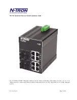
FRONT PANEL (712FX4)
From Top to Left:
RJ45 Ports
Auto Sensing 10/100 Base-TX Connections
Fiber Ports
100 Base-FX Connections
LED lights when Power is supplied to the unit
NOTE: The RJ45 data port has two LEDs located on each connector. The left LED indicates LINK status,
and the right LED indicates ACTIVITY.
LEDs: The table below describes the operating modes:
LED
Color
Description
GREEN
Power is ON
RED
Power is ON and a fault condition exists
OFF
Power is OFF
LNK
GREEN
10/100Mb Link between ports
OFF
No Link between ports
ACT
GREEN
Data is active between ports
OFF
Data is inactive between ports
Summary of Contents for 712FX4 Series
Page 1: ...712FX4 Managed Industrial Ethernet Switch User Manual Installation Guide...
Page 11: ...Revised 2012 05 01 Page 11 of 163 CLEANING Clean only with a damp cloth...
Page 33: ...Revised 2012 05 01 Page 33 of 163 Administration SNMP Continued...
Page 37: ...Revised 2012 05 01 Page 37 of 163 DHCP Server Setup Profiles Continued...
Page 40: ...Revised 2012 05 01 Page 40 of 163 DHCP Server Setup IP Maps Continued...
Page 46: ...Revised 2012 05 01 Page 46 of 163 DHCP Relay Local IP Setup Continued...
Page 52: ...Revised 2012 05 01 Page 52 of 163 Ports Configuration Continued...
Page 82: ...Revised 2012 05 01 Page 82 of 163 IGMP RFilter Continued Modifying rfilter port settings...
Page 90: ...Revised 2012 05 01 Page 90 of 163 N Ring Advanced Configuration Continued...
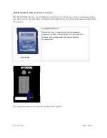
Page 113: ...Revised 2012 05 01 Page 113 of 163 If a Configuration Device is present that is presented...
Page 149: ...Revised 2012 05 01 Page 149 of 163...


