background image

(Revised 2013-06-21) 

11

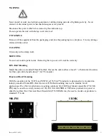
WARNING 

 
Never install or work on electrical equipment or cabling during periods of lightning activity.  Never 
connect or disconnect power when hazardous gasses are present. 


Disconnect the power cable before removing the enclosure top. 
Do not operate the unit with the top cover removed 


UNPACKING 


Remove all the equipment from the packaging, and store the packaging in a safe place.  File any damage 
claims with the carrier. 
 

CLEANING 


Clean only with a damp cloth. 


SERVICING 


No user serviceable parts inside.  Removing the top cover will void the warranty. 


DIN-Rail Mounting


Install the unit on a standard 35mm Din-Rail.  Recess the unit to allow at least 5” of horizontal clearance 
for fiber optic cable bend radius (2” for TX models). 


Panel and Rack Mounting 


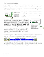
With the exception of the 524TX and 526FX2, all N-Tron™ products are designed to be mounted on 
industry standard 35mm DIN-Rail. However, DIN-Rail mounting may not be suitable for all 
applications. We offer two alternative mounting solutions: Our 900 Panel Mount Assembly (P/N: 900-
PM) may be used to securely mount our 100, 200, 300, 400,

 500

, or 900 Series products to a panel or 

other flat surface; Our Universal Rack Mount Kit (P/N: URMK) may be used to mount our products to 
standard 19" racks 


900-PM   


             URMK 


Summary of Contents for 508TX

Page 1: ...Revised 2013 06 21 1 500 Series Industrial Ethernet Switches Installation Guide...

Page 2: ...m Menu 23 N ViewTM Menu 23 Aging Menu 24 System Info 25 Restoring defaults 25 User Password 26 Switch Menu 27 Port Mirroring 27 MAC Based Trunking 29 QOS 31 VLAN 33 Tagged VLAN 34 Port VLAN 40 IGMP Sn...

Page 3: ...Revised 2013 06 21 3 Damp Heat IEC60068 2 30 Test Db 66 GOST R Certified 66 Key Specifications 524TX 67 Damp Heat IEC60068 2 30 Test Db 68 GOST R Certified 68 Key Specifications 526FX2 FXE2 69...

Page 4: ...S 517FX N XX S 526FX2 N XX S 508FXE2 N XX YY 509FXE N XX YY 517FXE N XX YY 526FXE2 N XX YY Where N N for N ViewTM A for Advanced Management Blank Otherwise XX ST or SC and YY 15 40 80 S Standard Tempe...

Page 5: ...ded but not limited to lost profits arising out of errors or omissions in this manual or the information contained herein Warning Do not perform any services on the unit unless qualified to do so Do n...

Page 6: ...se to the unit Units not properly grounded may result in a safety risk and could be hazardous and may void the warranty See the grounding technique section of this user manual for proper ways to groun...

Page 7: ...his product must be UL listed for the area in which it is installed 5 Only UL listed wiring with temperature ratings greater than 90O C permitted for Class I Div 2 installations operating at temperatu...

Page 8: ...sting shall be considered 5 The end user shall provide bonding means as necessary All bonding equipment components shall be evaluated according to EN 60079 15 2010 and covered by a component certifica...

Page 9: ...iber links are capable of 2 Kilometers of 100 Mb communications without the use of repeaters The 509FXE 517FXE 526FXE is a 9 17 26 port switch that is similar to the 509FX 517FX 526FX but with extende...

Page 10: ...Industry Standard 35mm DIN Rail Enclosure Optional N ViewTM Monitoring Optional Advanced Management Features Port Mirroring Mac Based Trunking Quality of Service traffic priority port or tagged VLAN...

Page 11: ...g the top cover will void the warranty DIN Rail Mounting Install the unit on a standard 35mm Din Rail Recess the unit to allow at least 5 of horizontal clearance for fiber optic cable bend radius 2 fo...

Page 12: ...cated at the top or bottom of each connector The left LED indicates LINK status green for 100Mb link Orange for 10Mb link and the right LED indicates ACTIVITY Green for Full Duplex activity Orange for...

Page 13: ...ll LED s will flash ON Momentarily Verify the Power LED stays ON GREEN 1 Note Only 1 plug must be connected to power for minimal operation For redundant power operation V1 and V2 plugs must be connect...

Page 14: ...ed PEM nut to connect a ground lug via a machine screw care should be taken to limit the penetration of the outer skin by less than 1 4 in Failure to do so may cause irreversible damage to the interna...

Page 15: ...Revised 2013 06 21 15 RJ45 Connector Crimp Specifications Please reference the illustration below for your Cat5 cable specifications...

Page 16: ...on com pdf nview_opc_user_guide pdf Once the software is installed you should view the Ports Counter page to remotely monitor each connected port You may find it helpful to copy Alt Print Screen the P...

Page 17: ...ater for 100Mbit Operation 6 For FX FXE models verify TX is connected to far end RX and vise versa Also insure the connecting partner is 100Mb s IEEE 100BaseFX compliant Note the 500 Series FX FXE swi...

Page 18: ...7 AF 00 05 26 N View is ENABLED Trunking Link Aggregation is DISABLED Mirroring is DISABLED Tagged QOS is DISABLED Port QOS is DISABLED VLAN is DISABLED IGMP Snooping is ENABLED Aging is ENABLED Manag...

Page 19: ...sword enter password admin then press Enter see section on user defined password Example Managing IGMP Snooping Exit to return to Management Console Function Press ESC to Exit Now in user interface mo...

Page 20: ...ig Configure Mirroring trunking Assign Port Trunking Groups info Get information about Trunking enable disable Enable Disable Trunking config Configure Trunking qos Quality of Service traffic priority...

Page 21: ...cast Filter On 508FX2 A only o dis_nring Disable filters for N Ring or en_nring if currently disabled o dis_ring600 Disable filters for 600 series ring or en_ring600 if currently disabled ports Reconf...

Page 22: ...version MAC address which functions are presently enabled SYSTEM Opens the SYSTEM menu The SYSTEM menu is used to set the system parameters SWITCH Opens the SWITCH menu You can make settings for the s...

Page 23: ...switch status via the LAN When enabled periodic Multicast MAC packets are sent out from every port Note The configuration console is only available with A models Command Description Comment info Displ...

Page 24: ...Comment info Displays the current Aging settings Default is 300 seconds except it is 20 seconds for 508FX2 and 526FX disable or enable Enable or Disable Aging Choice is opposite of current state conf...

Page 25: ...orts The Multicast addresses and group members are cleared After firmware version 8 09 the Router Multicast Data Filter is enabled on all ports Filtering Broadcast Filter is disabled All ports receive...

Page 26: ...ycle is required when completed The user password feature is available in firmware version 8 09 and subsequent For security reasons forgotten passwords can only be reset to factory defaults with the p...

Page 27: ...e choice is limited based on the source port Entries are ranged to prevent issues The destination port must be in the same group as the source port as below 1 through 8 and 25 9 through 16 17 through...

Page 28: ...stination Port one of 1 2 3 4 6 7 8 25 Enter Port Number or ESC to exit 9 Select Destination Port one of 1 2 3 4 6 7 8 25 Enter Port Number or ESC to exit 8 For Port Mirroring the Destination Port is...

Page 29: ...ir dynamically balances traffic and dynamically fails over If port 1 goes down ports 1 2 traffic is remapped to port 2 only If port 2 goes down ports 1 2 traffic is remapped to port 1 only If port 7 g...

Page 30: ...runk Pair Port 2 Port 1 Trunk Pair Port 7 Port 8 Port 4 If 509FX A Fiber port 9 Port 5 Port 6 Port 3 Port 8 Port 2 Port 1 Port 4 If 509FX A Fiber port 9 Port 5 Port 6 Port 3 Port 2 508TX A or 509FX A...

Page 31: ...ts have both QOS types disabled The A units have both QOS types disabled in default for version 7 08 and later firmware Tagged IEEE 802 1p Quality of Service QOS provides traffic priority based upon v...

Page 32: ...6 CLI SWITCH QOS Example of the Port QOS config screen CLI SWITCH QOS set_port Configure Port QOS Select higher priority ports These ports are higher priority for Port QOS none Enter ports to enable...

Page 33: ...tches one or more VLANs can be extended across a large network Notice that there is no change in Ethernet frames external to the switch with Port VLAN partitioning End stations are unaware of the VLAN...

Page 34: ...work administrators must ensure ports with non 802 1Q compliant devices attached are configured to transmit untagged frames Many network interface cards for PCs and printers are not 802 1Q compliant I...

Page 35: ...alue are denoted by parentheses as in YES Example of the Tagged VLAN config groupX screen taking default choices Note that for the defaults choices just enter all chosen ports have the group VID as th...

Page 36: ...r YES CLI no Enter ports to have PVID 325 Example 3 6 12 14 enter Enter Port Numbers or ESC to exit 1 3 4 5 For incoming pkts with tagged VID 325 the outgoing pkts are untagged for ports 1 2 3 4 5 6 1...

Page 37: ...tagged for ports 2 6 17 VLAN GROUP7 has VID 325 and includes Ports 1 2 3 4 5 6 17 GROUP7 outgoing pkts are untagged for ports 1 6 There is more Press SPACE BAR to continue or escape to exit For each p...

Page 38: ...is Enabled CLI SWITCH VLAN group2 Configure Tagged VLAN Group 2 Enter VID or ESC to exit 4 Enter ports to Join VLAN Group 2 Example 3 6 12 14 enter Enter Port Numbers or ESC to exit 1 2 3 4 5 6 7 8 9...

Page 39: ...GROUP2 outgoing pkts are untagged for ports 2 3 4 5 6 7 8 9 10 11 12 13 14 15 16 17 There is more Press SPACE BAR to continue or escape to exit For each port except port s 1 untagged incoming pkts wi...

Page 40: ...ps they ll be added to group1 and you ll see a message Port VLAN Menu Command Description Comment info Displays the current VLAN settings disable or enable Enable or Disable VLAN Choice is opposite of...

Page 41: ...SWITCH VLAN info Port VLAN is ENABLED All outgoing frames will be untagged VLAN GROUP1 includes Ports 10 11 12 13 14 15 16 17 VLAN GROUP2 includes Ports 1 2 3 4 5 VLAN GROUP3 includes Ports 4 5 6 7 8...

Page 42: ...ers or ESC to exit 4 5 Continued on next sheet CLI SWITCH VLAN port Wait Port VLAN selected CLI SWITCH VLAN enable Port VLAN is Enabled CLI SWITCH VLAN group2 Configure Port VLAN Group 2 Enter ports t...

Page 43: ...GROUP1 includes Ports 10 11 12 13 14 15 16 17 VLAN GROUP2 includes Ports 1 2 3 4 5 VLAN GROUP3 includes Ports 4 5 6 7 8 9 VLAN GROUP4 includes Ports 1 2 3 4 5 6 7 8 9 VLAN GROUP5 includes Ports none V...

Page 44: ...ly set and or automatically done Out of the box IGMP Snooping will function dynamically without intervention If some of the devices in the LAN do not understand IGMP then manual settings are provided...

Page 45: ...s see below In firmware version 8 09 and subsequent the default is that the Router Multicast Data Filter is enabled for all ports so any router ports do not get DATA frames with KNOWN multicast destin...

Page 46: ...ault Source IP Address is redundant to another in your topology and that this could create an issue in a device that is monitoring IGMP Queries AND mapping these Addresses to some other parameter In c...

Page 47: ...n as router switch link ports One does not have to manually enter anything unless accommodating non IGMP devices Ports 4 and 5 were automatically detected as router switch link ports Rfilter was appli...

Page 48: ...filter you will be asked to Enter ports that are to receive General Broadcast frames After entering sfilter you will be asked to enter the static multicast filter number 1 16 for 524 526 or static mul...

Page 49: ...le the group or ESC to Exit CLI 01005e010100 Enter ports that are to receive on this multicast address Use commas to separate port numbers Example 3 6 12 14 22 enter Enter Port Numbers or ESC to exit...

Page 50: ...enter anything for this purpose unless accommodating non IGMP devices 1 The entire 12 hexadecimal digits can be identified with a sniffer Or 2 The address can be calculated from a known class D addres...

Page 51: ...of the low order 23 bits of the class D IP address to the low order bits of the MAC layer destination Mapping of class D 226 129 1 10 IP address to MAC layer multicast The mapping of 226 129 1 10 to...

Page 52: ...d leave another in autonegotiate the default the unit in autonegotiation does not go into 10 full It goes into 10 half It gets no autonegotiation response It easily senses speed passively but has no w...

Page 53: ...t numbers Example 3 6 12 14 22 enter Enter Port Numbers or ESC to exit 1 2 3 4 9 10 11 12 13 CLI SWITCH PORTS Example of the negotiate screen CLI SWITCH PORTS negotiate Enter ports that are to autoneg...

Page 54: ...s Example 3 6 12 14 22 enter Enter Port Numbers or ESC to exit 1 7 19 CLI SWITCH PORTS Example of the Ports info screen CLI SWITCH PORTS info These ports are Enabled all ALL RJ45 ports are now set to...

Page 55: ...d if the bottom layer is composed of simultaneously multicasting devices Reference the figure below 3 In stage 1 all ports of any 500 series A switch may be connected to multicasting devices NOTE A fi...

Page 56: ...evices Reference the figure below 3 In stage 1 all ports of any 500 series A switch may be connected to multicasting devices NOTE A fiber ring backbone or trunked architecture is basically stage 1 for...

Page 57: ...t 9 0 Amp 0 6 ms 24VDC Input Ripple Less than 100 mV Environmental Operating Temp 40oC to 85oC Storage Temp 40oC to 85oC Operating Humidity 10 to 95 Non Condensing Operating Altitude 0 to 10 000 ft Sh...

Page 58: ...A FCC 47 CFR Part 15 Subpart B Class A EMS EN61000 6 2 EN61000 4 2 ESD EN61000 4 3 RS EN61000 4 4 EFT EN61000 4 5 Surge EN61000 4 6 Conducted Disturbances Conducted Low Frequency IEC60533 Shock IEEE 1...

Page 59: ...Operating 40oC to 85oC Storage Operating Humidity 10 to 95 Non Condensing Operating Altitude 0 to 10 000 ft Shock and Vibration Shock 200g 10ms Vibration Seismic 50g 5 200Hz Triaxial Note Unit must be...

Page 60: ...0 6 4 EN55011 Class A FCC 47 CFR Part 15 Subpart B Class A EMS EN61000 6 2 EN61000 4 2 ESD EN61000 4 3 RS EN61000 4 4 EFT EN61000 4 5 Surge EN61000 4 6 Conducted Disturbances Conducted Low Frequency I...

Page 61: ...erating 40oC to 85oC Storage Operating Humidity 10 to 95 Non Condensing Operating Altitude 0 to 10 000 ft Shock and Vibration Shock 200g 10ms Vibration Seismic 50g 5 200Hz Triaxial Note Unit must be B...

Page 62: ...EMI EN61000 6 4 EN55011 Class A FCC 47 CFR Part 15 Subpart B Class A EMS EN61000 6 2 EN61000 4 2 ESD EN61000 4 3 RS EN61000 4 4 EFT EN61000 4 5 Surge EN61000 4 6 Conducted Disturbances Conducted Low F...

Page 63: ...7 0 Amp 0 8 ms 24VDC Input Ripple Less than 100 mV Environmental Operating Temp 40oC to 85oC Storage Temp 40oC to 85oC Operating Humidity 10 to 95 Non Condensing Operating Altitude 0 to 10 000 ft Shoc...

Page 64: ...A FCC 47 CFR Part 15 Subpart B Class A EMS EN61000 6 2 EN61000 4 2 ESD EN61000 4 3 RS EN61000 4 4 EFT EN61000 4 5 Surge EN61000 4 6 Conducted Disturbances Conducted Low Frequency IEC60533 Shock IEEE 1...

Page 65: ...ion 517FX 20oC to 70oC Operating 40oC to 85oC Storage Operating Humidity 10 to 95 Non Condensing Operating Altitude 0 to 10 000 ft Shock and Vibration Shock 200g 10ms Vibration Seismic 50g 5 200Hz Tri...

Page 66: ...EMI EN61000 6 4 EN55011 Class A FCC 47 CFR Part 15 Subpart B Class A EMS EN61000 6 2 EN61000 4 2 ESD EN61000 4 3 RS EN61000 4 4 EFT EN61000 4 5 Surge EN61000 4 6 Conducted Disturbances Conducted Low F...

Page 67: ...current 1 0 A Inrush Current 9 5 Amp 0 75 ms 24VDC Input Ripple Less than 100 mV Environmental Operating Storage Temp 40oC to 85oC Operating Humidity 10 to 95 Non Condensing Operating Altitude 0 to 10...

Page 68: ...FR Part 15 Subpart B Class A EMS EN61000 6 2 EN61000 4 2 ESD EN61000 4 3 RS EN61000 4 4 EFT EN61000 4 5 Surge EN61000 4 6 Conducted Disturbances Conducted Low Frequency IEC60533 Shock IEEE 1613 250 mm...

Page 69: ...X2 20oC to 70oC Operating 40oC to 85oC Storage Operating Humidity 10 to 95 Non Condensing Operating Altitude 0 to 10 000 ft Shock and Vibration Shock 200g 10ms Vibration Seismic 50g 5 200Hz Triaxial R...

Page 70: ...6 4 EN55011 Class A FCC Title 47 Part 15 Subpart B Class A EMS EN61000 6 2 EN61000 4 2 ESD EN61000 4 3 RS EN61000 4 4 EFT EN61000 4 5 Surge EN61000 4 6 Conducted Disturbances Conducted Low Frequency...

Page 71: ...RANTIES EXCLUSIVE IF AN N TRON PRODUCT DOES NOT OPERATE AS WARRANTED ABOVE CUSTOMER S SOLE REMEDY FOR BREACH OF THAT WARRANTY SHALL BE REPAIR REPLACEMENT OR REFUND OF THE PURCHASE PRICE PAID AT N TRON...

Reviews: