The oNeTRAK Manual
The oNeTRAK Manual
SPECIFICATIONS
3
MODULES/LAYOUT SAMPLES
14
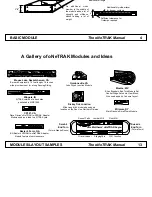
Standard NTRAK
layout
Junction module
"Gordonsville"
Offset module
module with
additional depth
180
°
return
loop module
corner
modules
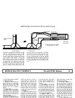
oNeTRAK part of the Orlando '98 Convention layout
Arrows show direction of traffic
on extended Red Line Route
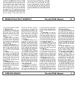
This was the first appearance of oNeTRAK in large
scale. The operating scheme extends the Red
Line Route through this part of the layout. The
Junction module (Gordonsville) permits both legs
of the Route to pass through. Trains enter
Gordonsville from the south on the right-hand
track. They pass through a turnout and head north
on single track. The engineer loops round
oNeTRAK's main and reenters Gordonsville from
the west. The train takes the right hand leg of the
wye and continues off the module back to the
south, this time on the second track. The straight
leg of the wye (at the front of the module) is never
used, so there is no reversing loop. An empty
boxcar is usually parked on this leg, awaiting
interchange and preventing operators from using
the track. Trains that remain on the oNeTRAK loop
during local operations can use the third leg of the
wye.
Most of these guidelines are based
on NTRAK standards.
1. HEIGHT OF TRACK Nominal
height is 40 inches. To make grades
longer than one module the module
interface on grades may need to be
changed from the 40 standard
height.
2. FRAME SIZES Frame lengths in
multiples of one foot. Twelve inches
is the minimum width. This width may
be increased up to an additional foot,
front or back for a total maximum
width of three feet.
3. MODULE INTERFACE Same as
NTRAK with one clamp and the stan-
dard 4.91" Atlas connector track sec-
tion. The frame on the module end
can be 1x3 or 1x4 lumber or plywood
equivalent.
4. TRACKS Code 80 track is stan-
dard. Code 55 is acceptable with
code 80 transitions at module inter-
face. Any Atlas, Peco or Micro Engi-
neering code 80 or code 55 turnouts
are acceptable. One track is re-
quired, additional through tracks are
permitted.
5. MINIMUM RADIUS is 18 inches
with appropriate easements. To pre-
vent binding the minimum length of
tangent between all reverse curves
must be 7 inches.
6. LOCATION OF TRACK On
straight modules the location of the
main has no impact on the loop of
modules and is not important, but
generally the track is set back 4 to 6
inches from the nominal front so that
the Fascia may be reasonably
aligned. Bump outs on the modules
are permitted, same as NTRAK.
Double or triple track should have
1.5-inch center spacing at the mod-
ule interface.
7. CORNERS Standard corners
can be 3 by 3 or 4 by 4 feet, etc. On
a standard corner the track should be
set back 6 inches from the nominal
front edge. This makes layout design
with inside corners easier. With track
set in 6" modules can be used as in-
side or outside corners and maintain
the one foot spacing increments.
8. CLOSING LOOP LAYOUTS
Due to the wide variety of frame sizes
and locations of tracks, some gaps
may develop in a loop layout. Most
large loops should be flexible enough
to close a gap by "scrunching" the
modules together. In some cases a
temporary bridge may be necessary.
This can be made by using a piece of
foam, some flex track and a bar
clamp to close the gap.
9. JUNCTIONS The smallest re-
commended junction is 3 by 5 feet.
10. GRADES 1.5 percent maxi-
mum across a dedicated set of mod-
ules. Grades on other modules can
be created with shims under legs of
modules. Grades suggest addition of
a helper district and helper engine
facility.
11. END TURNS are modules that
include a 180-degree curve in the
track. They should be a minimum of 2
by 4 feet to allow the 18-inch mini-
mum radius and easements. The dis-
tance between the ends of tracks on
an end turn must be three feet or
more in even foot increments.
12. TURNOUT SIZES All turnouts
should be number 6 or larger on the
mains, passing sidings and inter-
change tracks. Number 6 turnouts
are also encouraged in yards for bet-
ter operation.
13. ELECTRICAL The main line
has a red plug fastened the same
way as NTRAK. The white and 110
volt requirements are the same as
NTRAK. There are no special DCC
related wiring requirements. NTRAK
standards for wire gauge suffice.
14. SCENERY Any realistic scen-
ery is permitted. Round down hills on
the ends of modules so the view from
an adjacent flat module looks like
scenery. Colors for the fascia and
skirts should blend with the scenery
(generally shades of green or
brown). Do not use diorama dividers.
15. SKYLINE Skyboards or vertical
scenery flats are optional. In many
cases photography is easier if the
skyboard is removable.
16. PASSING SIDINGS To en-
hance operations most layouts
should include several passing sid-
ings. Clubs should try to include one
or more standard passing sidings in a
layout. A standard passing siding is a
set of two 1 by 4 feet modules with
turnouts at each end of the pair and
double track connecting the turnouts.
The resulting passing siding is about
seven feet long. Double or triple track
modules can be used to extend these
sidings.
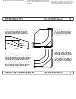
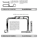
17. OFFSET MODULES provide
track offsets in one-foot increments
for visual variety. Observe 18-inch
minimum radius and tangent track
between reverse curves standards.
18. OPERATIONS SCHEME Al-
though a stated purpose of
oNeTRAK is to provide a venue for
more prototypical operations, no op-
erational scheme is specified. Clubs
and individuals can tailor the operat-
ing scheme to their situation. To in-
crease potential for realistic opera-
tion, wireless DCC is recommended.
19. LAYOUT DESIGN oNeTRAK
modules have proven very flexible in
layout design both as part of an
NTRAK layout or when standing
alone. Note that NTRAK modules
can be used in a 1T layout.


