background image


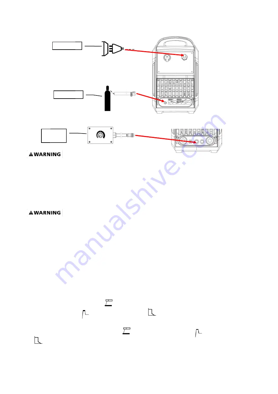
5. Input co


6. Foot cont


EXPO

Prolonged
begin weld
sleeved sh
 

OPERATI
 

High 

installation
protect the
have it che
any way a
receptacle
properly g


1. MMA: D

Set the

W

The hot st

the weldin

NOTICE

ca


Remo

cont

onnection m

trol pedal 


OSURE TO 

d exposure 

ding until yo

hirt, trouser

ION 


voltage  d

n of recept

e operator f

ecked by a 

and do not 

e. Make sur

rounded 22

C Stick arc

Welding mod

tart current 

ng materials

If set

Wel

an be adjust

Input powe

Gas cylind

ote 

trol box 

method 

A WELDIN

to the weld

ou are adeq

rs without c

danger from

tacle at the

from electri

qualified e

use any a

re the POW
20 VAC, 60 

c welding 

de knob

to


an

.  

lding mode k

ted.  

er  

der 

NG ARC IS

ding arc ca

quately pro

cuffs, high t

m power 

e power so

ical shock. 

lectrician. D

dapter betw

WER switch

HZ, single 

o  “

adj

d arc force c

knob

to “

11

S EXTREME

an cause bl

tected. Wea

topped sho

source! Co
urce. This 

If you are n

Do not cut 

ween the w

h is OFF th

phase, 50 a

ust the

Ad

current 

just the

ELY HARM

lindness an

ar flame-pro

oes, and an 

onsult a q

welder mu

not sure if y

off the grou

welder's pow

en connect

amp power 

djustment kn

can be 

e hot start cu

MFUL TO TH

nd burns. N

oof welding

ANSI appro

qualified e

ust be grou

your outlet 

unding pro

wer cord a

t your weld

source.


ob

to chan

adjusted at

urrent 


HE EYES A

Never strike
g gloves, a 

oved weldi

electrician 

unded while

is properly

ng or alter 

and the pow

der's powe

nge the weld

t this mode a

and arc fo

AND SKIN!
e an arc or

heavy long

ng helmet.

for proper

e in use to

y grounded,

the plug in

wer source

r cord to a

ding current.

according to

orce current


Summary of Contents for WAVE 200DIII

Page 1: ...nd understand all ASSEMBLY AND OPERATION INSTRUCTIONS before operating Failure to follow the safety rules and other basic safety precautions may result in serious personal injury 2015VERSION OWNER S MANUAL WELDING AND CUTTING TOTAL SOLUTION ...

Page 2: ...2 CATALOGUE GENERAL SAFETY RULES TECHNICAL SPECIFICATION KNOW YOUR WELDER INSTALLATION OPERATION TROUBLESHOOTING DIAGRAM PARTS LIST ...

Page 3: ...l arc rays shielded from the view of others Mount the welder on a secure bench or cart that will keep the welder secure and prevent it from tipping over or falling 1 2 Your Welder s Condition Check ground cable power cord and welding cable to be sure the insulation is not damaged Always replace or repair damaged components before using the welder Check all components to ensure they are clean and i...

Page 4: ...s Make sure your breathing air is clean and safe Work only in a well ventilated area or use a ventilation device to remove welding fumes from the environment where you will be working Do not weld on coated materials galvanized cadmium plated or containing zinc mercury or barium They will emit harmful fumes that are dangerous to breathe If necessary use a ventilator respirator with air supply or re...

Page 5: ...if handled improperly Do not touch welded materials with bare hands Do not touch TIG gun nozzle after welding until it has had time to cool down Sparks Flying Debris Welding creates hot sparks that can cause injury Chipping slag off welds creates flying debris Wear protective apparel at all times ANSI approved safety glasses or shield welder s hat and ear plugs to keep sparks out of ears and hair ...

Page 6: ...n Inspect it for good working condition prior to storage and before re use Notice If the welder continues to work too long time the Protection Indicator on the panel would be on indicating that the inner temperature rise inside the welder had exceed the designed permitted temperature At this time stop the welding work wait until the welder cooled inside and the Protection Indicator turned off then...

Page 7: ...ding Current A 5 170 5 170 Current Up Time S 0 15 0 15 Current Drop Time S 0 25 0 25 Pulse Frequency Hz 0 5 200 0 5 200 Pulse Width Adjustment DC 15 85 15 85 Clear Area Control AC 15 65 15 65 Gas Stop Delay Time S 0 30 0 30 Rated Duty Cycle 35 35 Cooling Type Air cooling Air cooling Effiency η 85 85 Power Factor Cosφ 0 92 0 92 Insulation Degree H H Cover Protection Degree IP IP21S IP21S Weight kg ...

Page 8: ... 220 12 16 4 5 KNOW YOUR WELDER Description WAVE200KDii is a digitization model can be used for MMA ACTIG DCTIG and PULSE TIG the parameters can be preset and showed welding current and voltage can real time display this is very easy operation 1 Front panel 1 1 Know the Front panel 1 2 Current display To show the preset current when setting and the welding current when working 1 3 AC DC transfer k...

Page 9: ...en working 1 10 Procedure parameter display This part is to show the procedure when the indicator lights the corresponding parameter can be adjusted with the adjustment knob See following details 1 Pre flow Time indicator light 8 Pulse frequency indicator light PULSE 2 Hot start current indicator light MMA 9 Background current indicator light PULSE 3 Arc starting current indicator light 4T 10 Minu...

Page 10: ...ding prong or alter the plug in any way Do not use any adapters between the welder s power cord and the power source receptacle Make sure the POWER switch is OFF when connecting your welder s power cord to a properly grounded 230 VAC 60 HZ Single Phase 50 Amp input power supply 2 EXTENSION CORD We do not recommend an extension cord because of the voltage drop they produce This drop in voltage can ...

Page 11: ... m power e power so ical shock lectrician D dapter betw WER switch HZ single o adj d arc force c knob to 11 S EXTREME an cause bl tected Wea topped sho source Co urce This If you are n Do not cut ween the w h is OFF th phase 50 a ust the Ad current just the ELY HARM lindness an ar flame pro oes and an onsult a q welder mu not sure if y off the grou welder s pow en connect amp power djustment kn ca...

Page 12: ...ils introduction is Technical Instruction 2 2 DC pulse TIG welding Set Welding mode knob to TIG AC DC transfer knob to DC Pulse switch set on Pulse would enter into the by Parameter knob Parameter positive knob Step1 Press this knob choose MMA the current display shows the pre set current voltage display shows the open circuit voltage Step2 Press this knob to choose the parameter Step3 Use this ad...

Page 13: ... and hold the torch trigger to activate the power source weld Release the torch trigger switch to cease welding NOTE in this operation mode the function of UP SLOPE and DOWN SLOPE is not used 2 3 2 4T Latch Mode This mode of welding is mainly used for long welding runs to reduce operator fatigue In this mode the operator can press and release the torch trigger and the output will remain active To ...

Page 14: ...b to adjust the Pre flow time Ic to adjust the welding current to adjust the stopping gas delay time to adjust the clear area width to adjust the AC square wave frequency Choose 2step 4step switch set on different gears to choose the welding method 2 step four step See the details introduction is Technical Instruction 2 5 AC pulse TIG welding Set Welding mode knob to TIG and AC DC transfer knob to...

Page 15: ...m the work piece by turning it so that gas nozzle rests against the work piece 2 ja 3 and the arc will ignite and the current will rise to the welding level within the up slope time 4 3 Stick welding skill 3 1 Welding positions There are two basic positions for welding Flat and Horizontal Flat welding is generally easier faster and allows for better penetration If possible the work piece should be...

Page 16: ...nse heat of the arc between the rod and the grounded metal melts the electrode and the flux For best performance on this unit we suggest the use of 6013 electrodes 3 5 SELECTING THE PROPER ELECTRODE There is no golden rule that determine the exact rod or heat setting required for every situation The type and thickness of metal and the position of the work piece determine the electrode type and the...

Page 17: ...rap metal which matches the metals you intend to work with to determine correct setting for your job The electrode type and the thickness of the work piece metal determine the amount of heat needed in the welding process Heavier and thicker metals require more voltage amperage whereas lighter and thinner metals require less voltage amperage Consult the welding electrode packaging for recommended w...

Page 18: ... get sticker or arc extinguishing When the rod is stuck to the work piece gently rock it back and forth to make them separate If not a short circuit will occur and it will break the welder A good arc is accompanied by a crisp cracking sound The sound is similar to that made by eggs frying To lay a weld bead only 2 movements are required downward as the electrode is consumed and in the direction th...

Page 19: ...low C Arc is too long D Ideal weld A solid weld bead requires that the electrode be moved slowly and steadily along the weld seam Moving the electrode rapidly or erratically will prevent proper fusion or create a lumpy uneven bead ELECTRIC SHOCK CAN KILL To prevent ELECTRIC SHOCK do not perform any welding while standing kneeling or lying directly on the grounded workpiece 3 7 6 Finish the bead As...

Page 20: ... ending on t e Current g Filler Wi e Types arc sets up s in the weld ng GTAW cess in wh e tungsten welding gr gon based the welding Ranges re Diamet 20 strains in the ing but relie W or TIG hich fusion non cons rade shield A filler me g applicati ter e metal joine ves the inte Tungsten n is produ sumable e ding gas o etal may al on ed by weldin rnal strains Inert Gas ced by an electrode a or weldi...

Page 21: ...en section ar he scope o g Material g is gene ncy While e applicab of this Op erally reg e many o ble a comp erating Ma 21 arded as of the pri prehensive anual a specia nciples o e outline o alised pro utlined in of the TIG cess that n the prev Welding p t requires vious Arc process is ...

Page 22: ...e temperature reduced Thermal relay broken Replace the thermal relay Over Lack voltage more Than 15 Become normal after voltage ok 5 Panel knob not adjustable Relevant potentiometer broken Replace the potentiometer Main PC board broken Replace the PC board Cable broken fallen off Find the disconnected wire and Connect reliably 6 No display on the AMP meter Digital Amp meter broken Change the meter...

Page 23: ...050640 2 jalousie 11 20050050643 1 Plastic back plate frame 12 11020011061 1 Fan cover 13 11050010100 1 Switching power supply board 14 11050100051 1 Pulse run on plate 15 20070550028 1 Gas valve 16 11010021176 1 The right side of the panel 17 11050110298 1 Rectifier inverter board 18 20050050194 4 Radiator support 19 20070430190 1 Rectifier heat sink 20 20050120030 1 Rectifier heat sink insulatin...

Page 24: ... 11050070218 1 Faceplate 34 11110340043 1 Hall 35 20070430191 1 Secondary rectifier heat sink down 36 20070280090 2 Fast recovery diode 37 20070430192 1 Secondary rectifier heat sink upper 38 11050110297 1 Secondary rectifier inverter board 39 20070120096 1 CBB Filter cap 40 20030300521 2 Resistance 1 41 11050110475 1 Gun switch isolation plate 42 11010021182 1 The back side of the panel 43 110500...

Page 25: ...25 ...

Reviews: