background image

MAINTENANCE  MANUAL 

VCE-MM-02 

19 

Wiring Diagram 


FAN

FAN

M

ot

or

En

cod

er

M

ot

or

En

cod

er

JP1

0

JP1

1

JP1

5

JP1

8

JP2

5

JP6

JP5

JP2

2

JP2

1

JP2

3

JP7

JP1

6

Pap

er

 R

ear

Sen

sor

Lev

er

Sen

sor

Se

ria

l P

or

t

US

Po

rt

JP1

JP3

JP4

JP3

0

JP2

7

JP3

3

JP8

JP3

1

JP2

8

JP2

0

JP1

0A

JP3

2

JP1

3

JP1

2

JP2

JP1

9

CR

 B

oa

rd

Pa

pe

r F

ro

nt

Sen

sor

Con

tr

ol

 P

an

el

Pow

er

 B

oa

rd

FR

ON

SI

D

E

RE

AR 

SI

D

E

: N

/C

M

AI

N

 B

O

AR

D

AC

 in

pu

t

100v

-240v

3A

 F

U

SE

On

/Off

Sw

itch

Pow

er

Bo

ar

d

D

40V

/5V

O

ut

put

Summary of Contents for ValueCut VC-1300

Page 1: ...No VCE MM 02 Cutting Plotter VC 600 VC 1300 VC 1800 MAINTENANCE MANUAL...

Page 2: ...ce parts Pinch Roller X Y axis belt Correction of dimension Specification list 02 Aug 14 2013 P9 P31 P32 P33 P34 P36 P37 P38 P39 Added VC 1800 Added serial information Added a notice of Firmware upgra...

Page 3: ...r soled shoes and stand on a dry surface If during the use of electrical equipment you feel an electrical discharge e g a tickling sensation on your skin immediately stop using that tool Label it and...

Page 4: ...System Diagram and Components of Main Board 17 System Diagram 18 Wiring Diagram 19 Maintenance 20 Components Replacement and Belt Tension Adjustment 20 Removing the Front Back End and Top Covers 20 R...

Page 5: ...52 Problems and Solutions 53 The line quality is not good enough at the corner or the end point 53 The position of pinch roller cannot be detected so that the media width cannot be determined correctl...

Page 6: ...MAINTENANCE MANUAL VCE MM 02 6 Recommend Service Parts List 57 Specification 61 Consumable Item List 62 Optional Item List 62...

Page 7: ...e provides system diagrams wiring diagrams and numerous flow charts detailing the maintenance diagnostics built into the ValueCut Cutting plotter Finally there is a parts list and spare parts order fo...

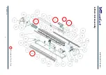
Page 8: ...MAINTENANCE MANUAL VCE MM 02 8 A Main Unit Assembly Recommend Service Parts...

Page 9: ...MAINTENANCE MANUAL VCE MM 02 9 B Electronic and Electrical Assembly Recommend Service Parts VC 1800 VC 600 1300...

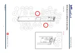
Page 10: ...MAINTENANCE MANUAL VCE MM 02 10 C Left End Assembly Recommend Service Parts...

Page 11: ...MAINTENANCE MANUAL VCE MM 02 11 D Right End Assembly Recommend Service Parts...

Page 12: ...MAINTENANCE MANUAL VCE MM 02 12 E X Motor Bracket and Belt Assembly Recommend Service Parts...

Page 13: ...MAINTENANCE MANUAL VCE MM 02 13 F Carriage Assembly Recommend Service Parts...

Page 14: ...MAINTENANCE MANUAL VCE MM 02 14 G Pinch Roller Assembly Recommend Service Parts...

Page 15: ...MAINTENANCE MANUAL VCE MM 02 15 H Main Beam Assembly Recommend Service Parts...

Page 16: ...MAINTENANCE MANUAL VCE MM 02 16 I Drum Assembly Recommend Service Parts...

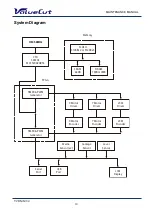
Page 17: ...MAINTENANCE MANUAL VCE MM 02 17 System Diagram and Components of Main Board...

Page 18: ...CF5206EAB54 FLASH 512KBx2 or 512KBx3 DRAM 1MB or 4MB SRAM 64KB TIMER PWM Generator TIMER PWM Generator X Motor Driver Y Motor Driver VCM Driver X Motor Encoder Y Motor Encoder VCM Encoder LCM Display...

Page 19: ...6 JP5 JP22 JP21 JP23 JP7 JP16 Paper Rear Sensor Lever Sensor Serial Port USB Port JP1 JP3 JP4 JP30 JP27 JP33 JP8 JP31 JP28 JP20 JP10A JP32 JP13 JP12 JP2 JP19 CR Board Paper Front Sensor Control Panel...

Page 20: ...onents of this machine Components Replacement and Belt Tension Adjustment Removing the Front Back End and Top Covers The following steps are those involved in removal of the front back end and top cov...

Page 21: ...following steps are those involved in replacing pinch roller sets To Unlatch the Pinch Roller Lever 1 Unscrew the two screws at each end of the Top Cover 2 Unplug the Control Panel Cable before remov...

Page 22: ...e Square Bar Holding Bracket To Remove the Pinch Roller Sets 1 Unscrew the 2 bracket screws 2 Remove the bracket and washer 1 Slide the pinch roller to the notch at the right end of the Square Bar 2 R...

Page 23: ...or coded by pressure force When replacing the pinch roller make sure to replace all the pinch rollers with the same color Replacing the Tool Carriage The following are those you must follow to success...

Page 24: ...l Carriage cover To Prepare the Tool Carriage for Removal 1 Depress the two locking clips at the top of the Tool Carriage Cover and pull the Cover away 1 Pop up the plastic locking pins using a flathe...

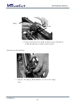
Page 25: ...M 02 25 To Remove the Tool Carriage 3 Unbolt and remove nut A and B and then unscrew both Bolt A and Bolt B until they are flush with the bracket Belt B Belt A 1 Separate the Sprung Washer Rollers as...

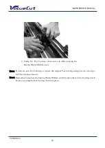
Page 26: ...ool Carriage simply reverse the steps for Tool Carriage removal Note2 Remember to separate the Sprung Washer Rollers and then place them on the Carriage track before you swing the Tool Carriage back i...

Page 27: ...the replacement of the Y motor 1 Loosen the all 3 tension bracket retaining screws as well as the tension adjustment screw but do not remove them 2 Depress the jumper clips and pull to unplug the 2 Y...

Page 28: ...Note2 After the Y motor is in place you must adjust the Y motor belt tension as described in the Y motor belt tension adjustment section of this chapter Note3 Make the Y motor jumper reconnection the...

Page 29: ...hat is involved in replacement of the VCM PC board Note1 If the Pinch Roller Sensor is still not effective after replacement the Tool Carriage or the Flat Cable may need replacement 2 Unplug the two s...

Page 30: ...is manual before installing or replacing any current carrying components T Parallel Port Connector o unplug the jumpers and connectors from the main board Note Please refer to the Wiring Diagram for m...

Page 31: ...osition changed as below refer to the below image from the Serial Interface connector RS 232C 9pin type machines Serial see below Remove the X motor before replacing the Main board VC 600 EVC2U0070 VC...

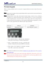
Page 32: ...s a tool for users to easily upgrade firmware followed by the steps listed below Port to use USB port Serial port Operation Down key Power on CUT TEST key Power on Note After firmware installation ple...

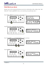
Page 33: ...values can be backed up even performing restore Press TOOL SELECT key and enter to tool setting menu Press key twice and display the restore menu Press CUT TEST key and ON OFF LINE key at the same ti...

Page 34: ...o Initialize all settings Initialize all settings Completely initialize all the settings including backed up AAS Offset X Y Scale length Width values Press TOOL SELECT key and enter to tool setting me...

Page 35: ...the same time Press ENTER key Press DATA CLEAR key Press ENTER key then all the setting values will be initialized Turn off the power after initialization BackUp Setting N ONLINE Ok ENTER Sure to Bac...

Page 36: ...e except backed up values Press TOOL SELECT key and enter to tool setting menu Press key twice and display the restore menu Press ENTER key Turn off the power after performing restore Select Ok ENTER...

Page 37: ...l L75354 AAS Offset X 0 6 Y 0 5 Scale Length Length 500 496 4 mm Width Length Width 500 500 2 mm AAS Offset setup steps Press the MICS key by OFF LINE mode to enter the Setup Menu then select AAS Offs...

Page 38: ...pops out for easy replacement as follows Note Position of the fuse inlet switch depends on the model VC 600 1300 Leftside VC 1800 Right side 1 With your fingers apply equal pressure to both of the ho...

Page 39: ...eing replaced 5 To tighten the tension turn the belt tension screw clockwise To loosen the tension turn the belt tension screw anticlockwise until the desired adjustment tension is reached The desirab...

Page 40: ...ce the push pull tension gauge s hook arm at the hole of X motor bracket and pull the motor toward yourself along the direction parallel to the racket edge and keep it at the 4kg tension position 1 Lo...

Page 41: ...do not remove them 2 Place the push pull tension gauge s hook arm at the hole of Y motor bracket and pull the motor toward yourself along the direction parallel to the line that passes through the mot...

Page 42: ...MAINTENANCE MANUAL VCE MM 02 42 Note The belt connecting the drive pulley and Y motor needs to be tightened up with a tension of 4 kg 3 Tighten the tension screw to retain the tension...

Page 43: ...find out which components are good or defective Using this diagnostic test facility enables the diagnosing of the hardware components How to Begin Maintenance Diagnostics To start the Maintenance Diag...

Page 44: ...nsors X Motor Encoder Y Motor Encoder Check USB Port System cannot go on testing LCM display current message more than 3 seconds Initial State XMb DRAM OK SRAM OK key key key key key key key key key k...

Page 45: ...lever sensor If the sensor is faulty the cutting plotter cannot sense that the pinch rollers have been lowered or not If the lever sensor is down you will see a lift the lever message on the LCM If th...

Page 46: ...tting plotter cannot detect the media length correctly You can see the current front and rear sensor condition you can turn it on or off to see if sensors are out of order or not or ENTER Key ON OFF L...

Page 47: ...carriage to the rightmost position the lever must be down to do this Once this is done please move the tool carriage to left Be careful when moving the tool carriage close to the pinch roller since t...

Page 48: ...rt such as a drum the tool carriage or the tool holder then examine the readings If the encoder reading changes dramatically the encoder is bad Refer to the maintenance chapter to replace the motor or...

Page 49: ...MAINTENANCE MANUAL VCE MM 02 49 Holder Encoder Test ENTER Key ON OFF LINE Key Seconds later Holder Encoder Select Ok ENTER Move Holder Up Down Wait for 3 seconds Holder Encoder Value 1234 ON OFF...

Page 50: ...nter a motor movement problem try to change the main board first If the problem still remains after replacing the main board try replacing the motor Drum Movement ENTER Key ON OFF LINE Key Forward Key...

Page 51: ...Key ENTER Key ON OFF LINE Key ENTER Key ON OFF LINE Key Left Key Carriage Movement Select Ok ENTER Y Motor Moving Now ON OFF Y Motor Moving Now Right ON OFF Y Motor Moving Now Left ON OFF Holder Down...

Page 52: ...TER Key ENTER Key ENTER Key ENTER Key ON OFF LINE Key ON OFF LINE Key ON OFF LINE Key ON OFF LINE Key Check RS 232 9600 Select Ok ENTER Receive file from PC 1048576 Byte ON OFF Check RS 232 19200 Sele...

Page 53: ...orrectly Causation and recovery Forgetting to lower the pinch roller Enable the pinch roller and push the lever forward to lower down the pinch roller The orientation of the width sensor on the carria...

Page 54: ...ct Adjust the belt tension X or Y motor belt tension is incorrect Adjust the belt tension The spring loading bearing of carriage is damaged Change the carriage set The length of the media is too short...

Page 55: ...the screws X or Y motor belt is loose Adjust the belt tension The carriage belt is loose Adjust the carriage belt tension The driver board set is damaged Change it The machine makes abnormal noise fr...

Page 56: ...ur cutting software package agent for help There are some communication errors Check the communication protocol There appears an unexpected tool force Causation and recovery The setting of tool force...

Page 57: ...C 1800 Location ME G290072900G 00 Control panel assembly MUT V V V A 13 ME G29005258G 00 Control Panel Board assembly V V V A 37 ME G234000330G 00 Control Panel Sticker MUT V V V A 5 ME G29005256G 00...

Page 58: ...Assembly VC6 L 120cm V F S20 ME G290071420G 00 Flat cable assembly VC13 L 195cm V F S20 ME G290071450G 00 Flat cable assembly VC18 L 250cm V F S20 ME G29002348G 00 Pinch roller Assembly V V V A 35 ME...

Page 59: ...ME G29004856G 00 Paper Sensor Assembly VC18 V H 15 ME G29004680G 00 Carriage assembly VC6 VC13 V V A 36 ME G29005316G 00 Carriage assembly VC18 V A 36 ME G29005378G 00 2 in 1 Cutter main board V V V B...

Page 60: ...NUAL VCE MM 02 60 Part no Part name VC 600 VC 1300 VC 1800 Location ME G20200003G 00 Pinch Roller V V V G 01 ME G20600009G 00 X axis Belt 2GT L210 W10 V V V D 01 ME G20600007G 00 Y axis Belt 2GT L172...

Page 61: ...is greater Repeatability 0 1mm Curve Arc Smoothing Yes Configurable Origin Yes Test Cut capability Yes Tangential Yes Repeat Yes Copy Yes Pouncing Yes Automatic Aligning System Completely Automatic Co...

Page 62: ...pcs box VC CBBK1 Cutting Blade Black Cap 42 0 175 1pcs box VC CBYE5 Cutting Blade Yellow Cap 25 0 25 5pcs box PSGB BK Pressurized Ballpoint Pen VC CMAT Cutting Pad 6mmx10m VC PT Pouncing Tool assembly...

Page 63: ...p www mutoh be MUTOH DEUTSHLAND GmbH Tel 49 0 211 385474 0 Fax 49 0 211 385474 74 E mail vertrieb mutoh gmbh de http www mutoh de MUTOH North Europe S A Tel 352 445 906 Fax 352 447 093 E mail info seg...

Reviews: