background image

RJ-900C series INSTALLATION MANUAL

7

RJ900CE-I-00

1

2

2

1

From the previous page
7.   Return the media loading lever to your front and 

close the front cover.

    The operation panel displays the media type setup 

    menu.
8.   Set the media type as Step 15-16 in "7 Loading

      the roll media".
    When the media type is entered, the operation panel 

    displays "Paper Initial", and 

    media starts the initial operation.
    After finishing the media initial operation, the 

    operation panel displays "Ready to Plot", and the 

    product turns to a normal operation.
    The media loading is complete.

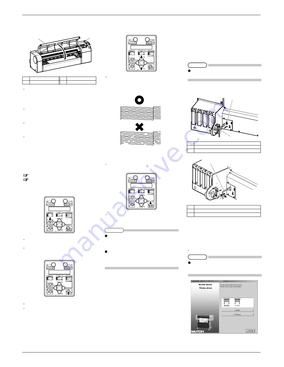
9 Check the printing condition

Check the print head condition after ink initial filling.

1.   Turn ON the power to the plotter, and set A3 or 

      larger sheet media or roll media.
        7 Loading the roll media
        8 Loading the sheet media
2.   Confirm that the plotter functions normally.
3.   Press the [Menu] key on the operation panel.

    It is displayed on the operation panel as "* Menu * 

    TestPlot >".
    The setup menu display will be displayed.
4.   Press [Enter] key on the operation panel.

    Operation panel displays  "TestPlot:  SetupPlot".
    Display shifts to Test print menu.

5.   Press the [Setting value +] key or [Setting value-] 

      key on the operation panel, select  "Nozzle check" 

      and press the [Enter] key.

    Perform the nozzle check printing.
6.   Check the print sample  and confirm that the 

      checked points are blurred or missing.

7.   If the nozzle check result indicates that the 

      checked points are blurred or missing, clean the 

      head.
    Press the [Cleaning] key on the operation panel for 

    at least 2 seconds.

    "Cleaning    ** min" is displayed on the operation

    panel.
8.   Start head cleaning.

9.   Perform the nozzle check again, and confirm the 

print head condition.

10 Installing the software

10.1 For network connection

This section explains how to connect to the Internet 

(TCP/IP).
1.   Turn ON the power to the plotter.
2.   Set the IP address for the plotter.

3.   Insert the network interface cable connector into 

      the network interface connector located on the 
      back of the plotter.

4.   Put the network interface cable to the cable clamp.

5.   Connect the another network interface cable 

      connector to the PC.
6.   Turn ON the power to the PC.
7.   Ensure that your PC boots up correctly, and insert 

      the CD-ROM on which "Windows plotter driver" 

      is written into the CD-ROM drive on your PC.
    Installer starts.

1

2

Pressing the [Cleaning] key again within one 

printing after the 1st head cleaning performs strong 

cleaning. If print blurs or incomplete printing is not 

fixed by one head cleaning, perform strong cleaning.

If several head cleanings does not remove print blur 

or incomplete printing, refer to the Operation 

Manual "6 Troubleshooting", and perform required 

 procedures.

 For details about the installing, refer to "3.7.2 

 Installing the plotter driver (for network connection)" 

 on the Quick Reference.

  No.

Name

Network interface cable

1
2

Network interface connector

  No.

Name

Network interface connector

1
2

Cable clamp

 Refer to "4.5.2.7 Network setup menu" in the 

 Operation Manual for setting the IP address.

 No.  

Name

             No.

    Name

   1         Media loading lever           2              Front cover

NOTE

TIP

TIP

Summary of Contents for RJ-900C series

Page 1: ...he instructions beginning on the next page 1 Unpacking boxes 1 1 Unpacking the plotter box 1 2 Unpacking the stand box 2 Confirming bundled items 2 1 Items in the plotter box 2 2 Items in the attachment box 2 3 Items in the stand box 3 Assembling 3 1 The stand assembling procedure 3 2 Assembling the stand 3 3 Detaching protective materials 4 Installation 4 1 Installation environment 4 2 Installati...

Page 2: ...llow ing steps 1 Carry the box to where you will unpack it 2 Open the box and take out the components 1 Plotter box 5 Attachment box 6 Installation Manual this manual 2 Scroller 3 Packing material 4 Handles RJ 901C only 2 Confirming bundled items After unpacking please confirm that the product has not damaged and no components are missing If any items are damaged or missing contact MUTOH local dea...

Page 3: ... Arm holder 6 Attach the media output tray as shown below No Name No Name 1 Hanger arm 3 Arm holder 2 Media output tray 7 Attach the book holder to the right side of the stand No Name No Name 1 Leg right 2 Book holder 8 Confirm that each component is fastened firmly by gently shaking the stand 3 2 Assembling the stand Attach the stand to the plotter in accordance with the following steps 1 Lock tw...

Page 4: ...tion place in accord ance with the list shown below 1 When using the plotter with the stand 1 Check that the two butterfly bolts attaching the stand and the plotter are not loose 2 Carry the plotter to the installation place 3 Lock two casters on the front side 4 Check that the two butterfly bolts attaching the stand and the plotter are not loose 2 When using the plotter only RJ 901C only 1 Carry ...

Page 5: ...e ink car tridge Follow the steps below to install the ink cartridge 1 Turn ON the product 2 The product starts the initial operation The operation panel displays KCMY cartridge 3 Take out the ink cartridge from the bag 4 Install the ink cartridge into the ink cartridge slot Insert the ink cartridge into the product with mark upside 5 Ink Refill min is displayed and the ink starts to be filled It ...

Page 6: ...th scroller to remove bending and slant of the media The media loading is complete 8 Loading the sheet media This section explains about how to load the sheet media Follow the steps below to load the sheet media 1 Turn ON the product 2 The product starts the initial operation The operation panel displays Paper End 3 Select Sheet media by pressing Back key on the operation panel Sheet media lamp li...

Page 7: ...ing clean the head Press the Cleaning key on the operation panel for at least 2 seconds Cleaning min is displayed on the operation panel 8 Start head cleaning 9 Perform the nozzle check again and confirm the print head condition 10 Installing the software 10 1 For network connection This section explains how to connect to the Internet TCP IP 1 Turn ON the power to the plotter 2 Set the IP address ...

Page 8: ...tings Utilities Perform cleaning and activate status monitor Plotter type 1 2 3 4 5 6 Plotter for which the operating state is to be checked is selected Residual ink quantity of K C M and Y color is displayed Residual ink quantity Media type residual quantity etc are displayed Plotter information Operating status of the plotter is displayed Update button Clicking it updates to the latest informati...

Reviews: