background image

1/17/18, 8'04 AM

Mutable Instruments | Anushri - Assembly instructions

Page 9 of 23

https://mutable-instruments.net/archive/anushri/build/

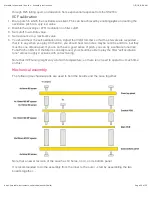
Add the IC sockets. It is strongly recommended to align the notch of the IC socket with the notch on
the symbol printed on the PCB.

9x DIP8.
3x DIP14.
7x DIP16.
1x DIP28.

Transistors, special resistors and capacitors

Summary of Contents for Anushri

Page 1: ...1 17 18 8 04 AM Mutable Instruments Anushri Assembly instructions Page 1 of 23 https mutable instruments net archive anushri build Anushri Assembly instructions...

Page 2: ...S AND PCB Main board schematics in PDF format Control board schematics in PDF format Main board top and bottom part placement Control board part placement You can find the Eagle files for this board i...

Page 3: ...nnector 12V ground ground ground 12V on the edge of the main board The rack mounting kit contains a spare panel that can be used to relocate the MIDI I O and the 6 35mm audio output to the front panel...

Page 4: ...chive anushri build Start with the 100 s decade 4x 220R resistors red red black black at positions R1 R3 R4 R13 11x 470R resistors yellow purple black black at positions R5 R6 R9 R10 R21 R22 R27 R51 R...

Page 5: ...position R28 3x 15k brown green black red at positions R18 R30 R35 10x 22k red red black red at positions R11 R14 R23 R26 R36 R40 R43 R44 R46 R47 1x 27k red purple black red at position R72 9x 33k or...

Page 6: ...100k s decade 9x 100k brown black black orange at positions R7 R8 R33 R34 R41 R42 R48 R60 R61 1x 150k brown green black orange at position R32 4x 200k red black black orange at positions R15 R58 R65 R...

Page 7: ...6 2x 3 6V Zener 1N5227B or BZX79 C3V6 at positions D3 and D4 1x 1N400x large power supply protection diode at position D2 1N4001 1N4002 1N4003 1N4004 only differ by their current voltage ratings all a...

Page 8: ...mbly instructions Page 8 of 23 https mutable instruments net archive anushri build 2x 10pF 100 at positions C20 C51 2x 18pF 180 at positions C54 C55 1x 100pF 101 at position C12 5x 560pF 561 at positi...

Page 9: ...9 of 23 https mutable instruments net archive anushri build Add the IC sockets It is strongly recommended to align the notch of the IC socket with the notch on the symbol printed on the PCB 9x DIP8 3...

Page 10: ...ransistor and 1x 2N5485 Check the symbol printed on the board for their alignment 1x 22nF film capacitor C4 2x 220pF styroflex capacitor C14 C28 1x 2 2nF styroflex capacitor C9 You can solder it to pi...

Page 11: ...nushri Assembly instructions Page 11 of 23 https mutable instruments net archive anushri build Electrolytic and tantalum capacitors Add 4x 4 7uF non polarized capacitors Just ignore the printed on the...

Page 12: ...le instruments net archive anushri build Add 5x 100uF electrolytic capacitors These parts are polarized the is printed on the PCB The negative lead is identified by a white stripe and a shorter lead A...

Page 13: ...s Anushri Assembly instructions Page 13 of 23 https mutable instruments net archive anushri build Power supply Add the two voltage regulators LM7805 and LM7905 These are two different parts don t mix...

Page 14: ...power switch You don t have to solder the power switch if you intend to mount the unit behind a Euro panel Connectors Add the main audio in out connectors unless you intend to mount the unit behind a...

Page 15: ...Instruments Anushri Assembly instructions Page 15 of 23 https mutable instruments net archive anushri build Solder the 4x male 2x8 connectors used to connect the two boards Note that they are on the...

Page 16: ...Page 16 of 23 https mutable instruments net archive anushri build Finally add the MIDI connectors That s it You can insert the IC Note that the TS912 used in the first batch of kits is now replaced by...

Page 17: ...ve anushri build Now let s move to the control board Add the 6x 220R resistors red red black black Add the 6x switches Add the 6x LEDs Note that they are polarized The symbol printed on the board show...

Page 18: ...erent kinds of pots Don t mix them up Add the 12x jack connectors It is recommended to solder only one leg the middle one of all of them first so that their position can be easily tweaked for optimal...

Page 19: ...or accurate pitch control Otherwise you can let the software tune the unit by holding the hold button and pressing run stop You should hear a low volume arpeggio played by the unit to measure the pitc...

Page 20: ...e intervals are respected that is to say when you play C3 then C4 you should hear two notes maybe not C3s and C4s but they must be one octave apart If you do not have a good sense of pitch you can try...

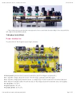
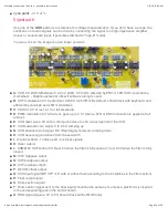
Page 21: ...wer distribution You can click on the image to open larger versions blue points ground can be used as a reference point for voltage measurements 1 Input DC voltage should be in the 7 5V 12V range pref...

Page 22: ...V at full amplitude D PWM modulation CV 0V at rest goes up to 4 1V when a LFO or ENV modulation is applied at full amount E VCO reset pulse 0V with a short pulse close to 5V at each period of the VCO...

Page 23: ...to the position of each potentiometer Moving a pot should change the height of a step in the sequence 11 DAC clock signal Bursts of two sequences of 8 steps at 10 MHz 12 DCO output signal 13 DAC1 sele...

Reviews: