background image

MAINTENANCE

25

WARNING: Always turn unit off, remove ignition key, and

disconnect the spark plug wire before making any

repairs or adjustments.

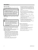
This snowthrower is equipped with two height adjust skids, secured

to the outside of the auger housing. These elevate the front of the

snowthrower.
When removing snow from a hard surface area such as a paved

driveway or walk, adjust the skids up to bring the front of the

snowthrower down.
When removing snow from rock or uneven construction, raise the

front of the snowthrower by moving the skids down. This will help to

prevent rocks and other debris from being picked up and thrown by

the augers.

ADJUST SKID HEIGHT

To adjust skids, proceed as follows:

1. Place a block (equal to height from ground desired) under

scraper bar near but not under skid.

2. Loosen skid mounting nuts (

A

, Figure 20) and push the skid

down (

B

) until it touches the ground. Retighten mounting nuts. 

3. Set skid on other side at same height.

NOTE: Make sure that snowthrower is set at same height on

both sides.

WARNING: Be certain to maintain proper ground

clearance for your particular area to be cleared.

Objects such as gravel, rocks, or other debris, if struck

by the impeller, may be thrown with sufficient force to

cause personal injury, property damage, or damage to

the snowthrower.

1. With the auger control lever released, the hook (

A

, Figure 21)

should barely touch the lever (

B

) without raising it. There can

be a maximum of 1/32 in. (0.8 mm) clearance.

2. To adjust, loosen the nut (

C

) by holding the adjusting flats (

D

)

and turning the nut. Then, turn the adjusting flats and hold the

adjustment screw (

E

). The adjustment screw is a phillips screw

and the head can be held or turned by inserting a screwdriver

through the spring (

F

).

WARNING: Do not over-tighten, as this may lift the

lever and cause the auger drive to be engaged

without depressing the auger drive control.

AUGER CONTROL CABLE ADJUSTMENT

WARNING: The auger must stop within 5 seconds. If it

does not, see an authorized dealer.

6. Release the auger control lever.
7. If the auger does not operate properly, stop the engine and

recheck the auger control cable adjustment.

8. If the drive linkage is properly adjusted, the tension of the

auger drive belt may require an adjustment (see authorized

dealer).

AUGER SHEAR PIN REPLACEMENT

The augers are secured to the auger shaft with special shear pins

that are   designed to break if an object becomes lodged in the

auger housing. Use of  a harder grade shear pin will reduce the

protection provided by the shear pin. 

WARNING: Do not go near the discharge chute or

auger when the engine is running. Do not run the

engine if any cover or guard is removed.

Under most circumstances, if the auger strikes an object which

could cause damage to the unit, the shear pin will break. This pro-

tects the gear box and other parts from damage.
The shear pins (

A

, Figure 22) are located on the auger shaft. Re-

place a broken shear pin as follows.

1. Tap out the broken shear pin with a pin punch.
2. Install a new shear pin and cotter pin. Bend the ends of the

cotter pin down.

IMPORTANT: Do not replace shear pins with anything

other  than the correct grade replacement shear pin. Use

of bolts, screws, or harder grade shear pins can result in

equipment damage.

3. Hold the adjusting flats and tighten the nut.
4. Start the engine and check the auger. The auger must not be

engaged unless the auger control lever is depressed.

5. With the engine running, fully depress the auger drive control

lever. The auger should engage and run normally.

Summary of Contents for 1695859

Page 1: ...Manuale dell Operatore fr Brukerh ndbok hu Haszn lati tmutat it N vod k obsluze lt Instrukcja obs ugi no pl Manuel d utilisation sl Uporabni ki priro nik sv Instruktionsbok Vartotojo vadovas Walkbehin...

Page 2: ...2...

Page 3: ...B 1 2 A B C 4 E A B D C 3 4 A 3 5 A B...

Page 4: ...3 1 1 2 x 2 7 16 6 7 5B 5A 2 17 lb ft 23 Nm 4 8 12 13 15 lb ft 20 Nm 11 10 9 4 6...

Page 5: ...5 8 B FULL 10 A A 11 A 1 2 Free HandTM Control 7 B A D C 9 A...

Page 6: ...16 A Full 17 A 6 12 A B C 13 14 15 A A B A B...

Page 7: ...7 20 B A 19 A B C 18 A B C 1 32 0 8mm 21 D E A C B F 22 A 23...

Page 8: ...8...

Page 9: ...r CE Identification Tag Product Reference Data The Illustrated Parts List for this machine can be downloaded from www murray com Please provide model and serial number when ordering replacement parts...

Page 10: ...ontrols section for the applicable symbols STOP Oil Fuel Fuel Shutoff Choke Off Choke On On Off Stop Slow Fast Auger Clutch Electric Start Engine Run Engine Stop Traction Control Auger Control Dischar...

Page 11: ...oper use of the snow thrower Make sure you are properly trained before operating the snowthrower Know how to stop the unit and disengage the controls quickly Never allow anyone to operate the snowthro...

Page 12: ...care Failure to observe these safety instructions can cause a fire or explosion which will result in severe burns or death Fuel Handling Keep the area of operation clear of all persons particularly sm...

Page 13: ...ll be thrown from the chute or jam in the auger Use extreme caution when operating on or crossing gravel drives walks or roads Adjust the collector housing height to clear gravel or crushed rock surfa...

Page 14: ...ice locations should be utilized for major service and repair requirements Use only attachments and accessories approved by the factory such as wheel weights counterweights or cabs Never attempt to ma...

Page 15: ...ow thrower read the safety decals as shown on your snow thrower The cautions and warnings are for your safety To avoid a personal injury or damage to your snow thrower understand and follow all the sa...

Page 16: ...tion of this manual INSTALL THE SPEED CONTROL ROD Attach the ball joint A Figure 4 located on the bottom end of the speed control rod B to the shift yoke assembly C with 5 16 lock washer D and 5 16 nu...

Page 17: ...ge chute to the left or right D Chute Deflector Wing Nut Used to control the angle of the chute deflector up or down E Free HandTM Control After engaging the traction control left hand and auger contr...

Page 18: ...manifold to ensure fast starts in cool weather D Safety Key Must be inserted to start engine Pull out to stop Do not turn safety key E Starter Cord Handle Used to start the engine manually F ON OFF Sw...

Page 19: ...and observe all the safety instructions in this manual Failure to do so will result in death or serious injury OPERATE THE SNOWTHROWER CAUTION Operation with a Snow Cab Wind may blow exhaust gasses ba...

Page 20: ...nd free from spilled gas oil and debris DISCHARGE CHUTE AND DEFLECTOR Discharge Chute Rotation Left Right 1 Turn the chute rotation crank A Figure 7 clockwise to rotate the chute to the right see Figu...

Page 21: ...butyl ether is acceptable NOTICE Do not use unapproved gasolines such as E85 Do not mix oil in gasoline or modify the engine to run on alternate fuels This will damage the engine components and void...

Page 22: ...he safety key Keep the safety key in a safe place The engine will not start without the safety ignition key START THE ENGINE Be sure that engine oil is at FULL mark on the oil fill cap dipstick The sn...

Page 23: ...below the scraper bar see Adjust Skid Height in the Maintenance section of this manual Rocks and gravel must not be picked up and thrown by the machine 6 After the snowthrowing job has been completed...

Page 24: ...fill cap and drain oil into a suitable container Replace oil drain plug and tighten securely Refill crankcase with the recommended motor oil Below 40 F 4 C the use of SAE 30 will result in hard start...

Page 25: ...head can be held or turned by inserting a screwdriver through the spring F WARNING Do not over tighten as this may lift the lever and cause the auger drive to be engaged without depressing the auger...

Page 26: ...handle back 11 If the machine must be stored outdoors block up the snowthrower and ensure the entire machine is off the ground Cover the snowthrower with a heavy tarpaulin STORAGE WARNING Never store...

Page 27: ...tor out of adjustment or needs lubrication See authorized dealer Engine fails to start Key is off Push key in to the ON position Failure to prime a cold engine Press primer button twice and start Fuel...

Page 28: ...lt loose or damaged See authorized dealer Traction control out of adjustment See authorized dealer Worn or damaged friction disc See authorized dealer Unit fails to discharge snow Auger control cable...

Page 29: ...ng for individual gas engine models is labeled in accordance with SAE Society of Automotive Engineers code J1940 Small Engine Power Torque Rating Procedure and rating performance has been obtained and...

Page 30: ...www murray com 30...

Page 31: ...zen ch m stech P i kontaktov n va eho autorizovan ho prodejce kv li n hradn m d l m servisu i informac m MUS TE m t tato sla REFEREN N DAJE V ROBKU N zev slo popisu modelu V robn slo jednotky S RIOV s...

Page 32: ...st Vlastnost a ovl d n STOP Olej Palivo Vypnut paliva Vypnut syti Zapnut syti Zapnuto Vypnuto Zastavit Pomalu Rychle Spojka neka Elektrick startov n B h motoru Zastaven motoru zen trakce zen neka V sy...

Page 33: ...e v te jak rychle p stroj zastavit a deaktivovat Nikdy nedovolte aby s p strojem zach zely osoby bez dn ch pokyn Jestli e m b t fr za ulo ena po del dobu v dy postupujte podle pokyn v n vodu k obsluz...

Page 34: ...velice opatrn Nedodr en t chto bezpe nostn ch pokyn m e v st k po ru i explozi kter zp sob v n pop leniny nebo smrt Zach zen s palivem Udr ujte pracovn oblast bez osob zvl t pak mal ch d t a zv at D...

Page 35: ...viny hra ky ukryt pod sn hem m e v st k jejich vyhozen nebo k ucp n neka D vejte si velk pozor p i p ekra ov n vjezd chodn k i silnic Um st n sb ra e nastavte tak aby se nedot kal t rku nebo povrchu z...

Page 36: ...e jejich p ry jsou ho lav VAROV N Startov n motoru vede k jiskr m Jiskry mohou zap lit bl zk ho lav plyny M e doj t k po ru nebo explozi Nedot kejte se hork ho motoru nebo tlumi e P ed dotykem vy kej...

Page 37: ...m sn hov fr zy si p e t te bezpe nostn n lepky kter jsou na va sn hov fr ze Upozorn n a varov n jsou pro va i bezpe nost Aby se p ede lo poran n i po kozen sn hov fr zy porozum jte t mto bezpe nostn m...

Page 38: ...OSTI P ipojte kulov kloub A Obr zek 4 um st n na spodn m konci ty e ovl d n rychlosti B k ad c vidlici C s pomoc 5 16 palce pru n podlo ky D a 5 16 palce matice E VAROV N P i mont i fr zy v dy pou vej...

Page 39: ...C H del rotace labu Pou v se k rotaci odpadov ho labu doleva i doprava D K dlov matice deflektoru labu Pou v se ke zm n hlu deflektoru labu nahoru a dol E Free HandTM ovlada Po aktivaci zen trakce lev...

Page 40: ...tilo rychl startov n za chladn ho po as D Bezpe nostn kl Mus b t vlo en p i startov n motoru Vyt hn te ho k zastaven Bezpe nostn m kl em neot ejte E Dr k startovac ho kabelu Pou v se k manu ln mu nast...

Page 41: ...a dol odhazov n sn hu Viz Odpadov lab a odchylova v t to sti VAROV N BEZPE NOSTN TESTY SN HOV FR ZY Test 1 nek Rotor Uvoln te ovlada neka prav ruka nek rotor se zastav b hem m n ne 5 sekund Test 2 Tr...

Page 42: ...vzd lenost Nebo odchylova sni te k z sk n men ho proudu a men vzd lenosti 3 Po z sk n po adovan ho hlu ut hn te k dlovou matici www murray com 20 OVL D N ZASTAVEN SN HOV FR ZY 1 Uvoln te p ku ovlada e...

Page 43: ...nebo do 15 MTBE methyl tercio butyl ether POZN MKA Nepou vejte neschv len benz ny jako nap klad E85 Nep id vejte do benz nu olej ani neupravujte motor pro provoz s alternativn mi palivy Do lo by k po...

Page 44: ...l udr ujte na bezpe n m m st Motor nen bez bezpe nostn ho startovac ho kl e mo no nastartovat Motor nastartujte n sleduj c m zp sobem 1 Zkontrolujte mno stv oleje 2 Ujist te se e ovlada e pohonu za ze...

Page 45: ...stli e je to mo n sn h by se m l odhazovat ve sm ru v tru 4 Pro norm ln pou it nastavte smyky 3 mm 1 8 palce nad krabac li tou Pro velice hutn sn h je ke zv en innosti mo no upravit smyky sm rem nahor...

Page 46: ...hn te ji Klikovou h del znovu napl te doporu en m motorov m olejem Syntetick 5W 30 P i teplot ch pod 4 C 40 F povede pou it SAE 30 k obt n mu startov n P i teplot ch nad 27 C 80 F povede pou it 10W 30...

Page 47: ...OV N Nep etahujte jeliko to m e v st ke zvednut p ky a zp sobit aktivaci pohonu neka bez stisku p ky neka PRAVA KABELU ZEN NEKA 1 P i uvoln n p ce ovl d n neka by se m l h k A Obr zek 21 sotva dot kat...

Page 48: ...pr vn ZKONTROLUJTE PNEUMATIKY Zkontrolujte zn mky po kozen na pneumatik ch Tlak pneumatik p ekontrolujte s pomo p esn ho m c ho n stroje viz Obr zek 23 POZOR Vyvarujte se poran n P i nespr vn m servis...

Page 49: ...opr vn n ho prodejce Motor nestartuje Kl je vypnut Kl zatla te do ZAPNUT polohy Selh n p i p prav studen ho motoru Tla tko p pravy stiskn te dvakr t a znovu startujte Palivov ventil je v ZAV EN poloze...

Page 50: ...epohybuje dop edu ani dozadu Hnac emen je uvoln n nebo po kozen Kontaktujte opr vn n ho prodejce Ovlada trakce je mimo polohu Kontaktujte opr vn n ho prodejce Opot ebovan i po kozen frik n kole ko Kon...

Page 51: ...dn nafukov n viz strana pneumatiky INFORMACE O V KONU MOTORU Hodnocen v konu jednotliv ch model motor je v souladu s kodexem SAE Society of Automotive Engineers J1940 Postupy pro hodnocen v konu mal...

Page 52: ...www murray com 30...

Page 53: ...chenden Feldern an Diese Nummern stehen auf den jeweiligen abgebildeten Teilen Sie M SSEN ber diese Angaben verf gen um Ersatzteile Serviceleistungen oder Informationen vom zugelassenen Fachh ndler zu...

Page 54: ...ich der verwendeten Symbole STOP l Kraftstoff Kraftstoffabs perrung Choke Aus Choke Ein Ein Aus Stopp Langsam Schnell Schneckenk upplung Elektrischer Start Betrieb des Motors Motorstopp Antriebss teue...

Page 55: ...ten bei der Nutzung der Schneefr se mit den Steuerungen vertraut sein Sorgen Sie daf r dass Sie vor Nutzung der Schneefr se entsprechend geschult wurden Sie m ssen wissen wie Sie die Einheit und die S...

Page 56: ...sionsgefahr Gehen Sie besonders sorgf ltig mit dem Kraftstoff um Die Nichtbeachtung dieser Sicherheitshinweise kann Ursache eines Feuer oder einer Explosion sein die Branndsch den und Todesf lle mit s...

Page 57: ...vor wenn Sie auf Wegen Pfade oder Stra en aus Schotter arbeiten oder diese berqueren Stellen Sie die H he des Sammlgeh uses auf R umung von Schotter oder Kiesoberfl chen ein Betreiben Sie die Schneefr...

Page 58: ...der Naturgas so sollte der Motor nicht gestartet werden Verwenden Sie keine Starthilfe Sprays da deren D mpfe leicht entz ndbar sind WARNUNG Beim Starten des Motors entstehen Funken Die Funken k nnen...

Page 59: ...utzen lesen Sie die Sicherheitsschilder auf Ihrem Ger t Die Warnungen und Hinweise dienen Ihrer Sicherheit Um Verletzungen oder Sch den durch oder an Ihrer Schneefr se zu vermeiden folgen Sie alle Sic...

Page 60: ...B befindet an das Bauteil Gabelschaltung C mit einem 5 16 Zoll Sicherungsring D und einer 5 16 Zoll Mutter E WARNUNG Ziehen Sie immer eine Schutz oder Sicherheitsbrille w hrend der Montage der Schneef...

Page 61: ...D Fl gelmutter des Kanalleitblechs Sie wird verwendet um den Winkel des Kanalleitblechs zu bestimmen herauf oder runter E Free Hand Steuerung Nach dem Anschalten der Antriebssteuerung linke Hand und d...

Page 62: ...tter erm glicht D Sicherheitsschl ssel Er muss eingef hrt werden um den Motor zu starten Zum stoppen ziehen Drehen Sie den Sicherheitsschl ssel nicht E Starter Schnur Sie wird verwendet um den Motor m...

Page 63: ...rechts des Aufwurfkanals festzusetzen Siehe Auswurfkanal und Lenkblech in diesem Abschnitt WARNUNG SICHERHEITSTESTS AN DER SCHNEEFR SE Test 1 Schnecke Gebl serad Die Steuerung des Fr swerks rechts lo...

Page 64: ...ich w hrend ihres Betriebes in ihrer N he aufhalten WARNUNG Lesen Sie sich vor der Inbetriebnahme die Gebrauchanleitung aufmerksam durch Die Maschine kann bei nicht ordnungsgem en Gebrauch gef hrlich...

Page 65: ...in l mit dem Benzin mischen Den Motor nicht so modifizieren dass er mit alternativen Kraftstoffen laufen kann Bei Nichtbeachtung dieser Punkte werden Motorkomponenten besch digt und die Motorgarantie...

Page 66: ...auf HINWEIS Verlieren Sie den Sicherheitsschl ssel nicht Bewahren Sie den Schl ssel an einem sicheren Ort auf Der Moter l sst sich ohne Sicherheitsschl ssel Z ndschl ssel nicht starten Starten Sie den...

Page 67: ...llen Sie die Gleitkufen auf 3 mm 1 8 Zoll unterhalb des R umschilds ein F r extrem harte Schneeoberfl chen k nnen die Gleitkufen f r eine bessere Leistung h her gestellt werden 5 Auf Schotter oder Kie...

Page 68: ...Abgassystems bzw kompletter Systeme k nnen von jeder Reparaturwerkstatt bzw jedem Mechaniker durchgef hrt werden Um jedoch kostenlosen Service am Abgassystem zu erhalten muss die Arbeit von einem vom...

Page 69: ...erade so ber hren ohne ihn anzuheben Der Freiraum kann maximal 0 8 mm 1 32 Zoll betragen 2 L sen Sie zum Einstellen die Mutter C indem Sie die Einstellfl chen D festhalten und die Mutter drehen Anschl...

Page 70: ...einen lwechsel vor der Lagerung bewahren Sie die optimalen Leistungsverh ltnisse f r Ihr Ger t nur 4 Zyklen 3 Schmieren Sie den Bereich um die Kolbenspitze Zylinder Daf r entfernen Sie zuerst die Z nd...

Page 71: ...t alle Tanken Sie den Kraftstoffbeh lter auf Choke is AUS kalter Motor Drehen Sie den Choke auf EIN stellen Sie den Gasgriff auf SCHNELL Motor ist abgesoffen Schalten Sie den Choke auf AUS und versuch...

Page 72: ...uches oder wenden Sie sich an einen zugelassenen H ndler Fr swerksteuerungsseilzug ist nicht richtig angepasst Fr swerksteuerungsseilzug anpassen Siehe Pr fen und Einstellen der Seilz ge im Abschnitt...

Page 73: ...enem Motor ist in bereinstimmung mit dem SAE Society of Automotive Engineers Code J1940 Small Engine Power Torque Rating Procedure angegeben und die Bewertung der Leistung wurde in bereinstimmung mit...

Page 74: ...30 www murray com...
Reviews: