SN8000 EVK User Guide
Page 9 of 30
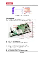
Reset button
Application button
Application LED
Serial flash (8M bits) and interface connectors
UART interface connectors
Ribbon connector to select I/O pins of the SN8000 module
Pads for header to access select I/O pins of the STM32F
2.2.1 Programming and debug interface
The SN8000 EVB provides a mechanism for programming and debugging applications on the STM32F
through the USB-JTAG interface. The instructions for installing the driver for the USB-JTAG interface are
described in Section 2.4.
2.2.2 UART interface
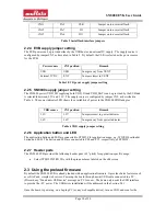
The EVB also provides a serial interface to the STM32F processor through the USB-UART interface. The
instructions for installing the driver for that interface are described in Section 2.4. Connectors CN4-CN7
may be removed to disconnect the USB-UART interface. The ordering of the jumpers in the illustration
below listed from top to bottom is CN4, 5, 6, 7 and 8. The left column of the pins is connected to the USB-
UART port, and the right column is connected to STM32F. Jumper on CN8 should be removed.
Connector
STM32F pins
Signal
Remark
CN4
PA12
RTS/
Jumper on to use USB-UART interface
CN5
PA11
CTS/
Jumper on to use USB-UART interface
CN6
PA9
TXD
Jumper on to use USB-UART interface
CN7
PA10
RXD
Jumper on to use USB-UART interface
Table 1 UART interface jumpers
2.2.3 Serial flash
The EVB has an 8MBits Winbond W25Q80BL ([4]) serial flash that may be used for over-the-air FW
upgrade by the WICED SDK (Section 2.4). The jumpers on connectors CN10-CN12 may be removed to
disconnect the serial flash from the module so that those pins may be connected to the customer platform
for other purposes. The ordering of the jumpers in the illustration below listed from left to right is CN10,
11, 13 and 12. The bottom row of the pins is connected to the serial flash, and the top row is connected to
STM32F.
Serial flash interface
(CN10, 11, 13, 12)
Serial flash
Connector
STM32F pins
Flash Signal
Remark
CN10
PA4
CS/
Jumper on to use serial flash


