background image

PAGE 40 — DCA-100SSJU — PARTS AND OPERATION  MANUAL (STD) — REV. #2  (05/03/01)

Voltage Selector Switch- 3 Phase 240/139V Position
The following are additional voltages available when the
voltage selector switch is in the 3 phase 240/139V
position.  (See Figure 31 below.)

3 Phase, 240V, 220V, or 208 Volt
The following connection, with the voltage selector switch
locked into the 3 phase 240/139V position (See Figure 31),
can offer THREE PHASE power at 270V, 220V, or 208V.
After hooking up the hard wires to the lugs as shown in
figure 33 below, 240V will be the voltage with the Voltage
Regulator Knob turned toward maximum.  220 volt will be
reached when the Voltage Regulator Knob is turned down,
and 208 volt when the Voltage Regulator Knob is toward
the lowest setting (See Figure 32).

Single Phase: 240V, 220V, or 208 Volt
The following connection, with the voltage selector switch
locked into the 3 phase 240/139V position (See Figure 31),
can offer SINGLE PHASE power at 240V, 220V, or 208V.
After hooking up the hard wires to the lugs as shown in
figure 34 below, 240V will be the voltage with the Voltage
Regulator Knob turned toward maximum.  220 volt will be
reached when the Voltage Regulator Knob is turned down,
and 208 volt when the Voltage Regulator Knob is toward
the lowest setting (See Figure 32).

Single Phase: 139V, 127V, or 120V
The following connection, with the voltage selector switch
locked into the 3 phase 240/139V position (See Figure 31),
can offer SINGLE PHASE power at 139V, 127V, or 120V.
After hooking up the hard wires to the lugs as shown in
figure 35 below, 139V will be the voltage with the Voltage
Regulator Knob turned toward maximum.  127 volt will be
reached when the Voltage Regulator Knob is turned down,
and 120 volt when the Voltage Regulator Knob is toward
the lowest setting (See Figure 32).

FIGURE 31.  Voltage Selector Switch 240/139V Three Phase

Position

FIGURE 32.  Voltage

Regulator Knob located

on the control panel

FIGURE 33.  Hard Wire Hookup for Three Phase 240V, 220V,

or 208V

FIGURE 34.  Hard Wire Hookup for Single Phase 240V, 220V,

or 208V

FIGURE 35.  Hard Wire Hookup for Single Phase 139V, 127V,

or 120V

DCA-100SSJU — OUTPUT TERMINAL PANEL OVERVIEW

Summary of Contents for Power WHISPERWATT DCA-100SSJU

Page 1: ...A 90746 FAX 800 672 7877 310 537 3700 SERVICE DEPARTMENT 800 421 1244 800 835 2551 FAX 310 537 3927 FAX 310 638 8046 E mail mq multiquip com www multiquip com PARTS AND OPERATION MANUAL MQ POWER DCA 1...

Page 2: ...PAGE 2 DCA 100SSJU PARTS AND OPERATION MANUAL STD REV 2 05 03 01...

Page 3: ...MODEL AND SERIAL NUMBER ON HANDWHEN CALLING PARTS DEPARTMENT 800 427 1244 or 310 537 3700 FAX 800 672 7877 or 310 637 3284 SERVICE DEPARTMENT 800 835 2551 or 310 537 3700 FAX 310 638 8046 WARRANTY DEP...

Page 4: ...nents 25 Dimensions 26 Control Panel Descriptions 28 29 Engine Operating Panel w key 30 31 Engine Operating Panel w MPEC 32 33 OutputTerminal Panel Overview 34 41 Installation 42 43 Pre Setup 44 47 Lo...

Page 5: ...ude complete part numbers and are received by fax qualify for the following extra discounts Number of line items ordered Additional Discount 1 9 items 3 10 items 5 Now Direct TOLL FREE access to our P...

Page 6: ...ould not be operated by persons under 18 years of age NEVER operate this equipment without proper protective clothing shatterproof glasses steel toed boots and other protective devices required by the...

Page 7: ...ttimefortheengineandgenerator to cool before performing maintenance Radiator 1 Radiator Cap Removing the radiator cap while the engine is hot will result in high pressurized boiling water to gush out...

Page 8: ...rength When lifting the generator always use the balanced center point suspension hook and lift straight upwards NEVER allow any person or animal to stand underneath the machine while lifting When loa...

Page 9: ...andfirstaidkit Knowthelocationofthenearesttelephone Also know the phone numbers of the nearest ambulance doctor and fire department RULES FOR SAFE OPERATION Maintenance Safety NEVER lubricate compone...

Page 10: ...tire tread wear on both vehicles ALWAYS make sure the trailer is equipped with a Safety Chain DCA 100SSJU TOWING RULES FOR SAFE OPERATION ALWAYS attach trailer s safety chain to bumper of towing vehi...

Page 11: ...iler DCA 100SSJU TRAILER SAFETY GUIDELINES CAUTION ALWAYS make sure the trailer is in good operating condition Check the tires for proper inflation and wear Also check the wheel lug nuts for proper ti...

Page 12: ...N O N S B L 0 9 9 2 0 2 1 6 6 B L 0 0 8 L E E H W T L I T L L U F W 0 7 R L R T 0 7 0 6 5 4 A C D O N E G R U S S B L 0 0 0 7 6 8 1 7 7 B L 0 0 0 2 D A P T A L F X 0 7 R L R T 0 7 0 6 5 4 A C D T P O...

Page 13: ...5 0 2 4 S A I B 5 X 4 1 s b l 0 0 5 3 3 G U L 5 F A E L 5 R E B B U R E L O P 4 T A L F X 0 7 R L R T S S A L C L L A B 2 E L B A T S U J D A 3 C 4 1 5 0 2 4 S A I B 5 X 4 1 s b l 0 0 5 3 3 G U L 5 F...

Page 14: ...raking Brake lockup grabbiness or harshness is due to lack of synchronization between the tow vehicle and the trailer being towed or under adjusted brakes Before any brake synchronizations adjustments...

Page 15: ...e adjusted in the same manner as electric brakes Brake lines should be periodically checked for cracks kinks or blockage Figure 3 below displays the major hydraulic air surge brake components that wil...

Page 16: ...factor in preservingtirelife Pressureshouldbecheckedcoldbefore operation DO NOT bleed air from tires when they are hot Check inflation pressure weekly to insure the maximum tire life and to prevent pr...

Page 17: ...5 3 5 6 0 5 3 1 5 2 0 2 0 4 5 3 5 6 0 5 4 1 5 2 0 2 0 6 0 5 0 2 1 0 9 5 1 5 2 0 2 0 6 0 5 0 2 1 0 9 6 1 5 2 0 2 0 6 0 5 0 2 1 0 9 Lug NutTorque Requirements It is extremely important to apply and mai...

Page 18: ...PAGE 18 DCA 100SSJU PARTS AND OPERATION MANUAL STD REV 2 05 03 01 NOTE LIGHTS ARE ORIENTED FROMTHE DRIVER S SEAT DCA 100SSJU TRAILERWIRING DIAGRAMS...

Page 19: ...EAK BRAKES OR BRAKES PULL TO ONE SIDE IS THERE GREASE OR OIL ON MAGNETS OR LININGS CLEAN OR REPLACE IS THE CONNECTIONS CORRODED CLEAN AND CORRECT CAUSE OF CORROSION IS THE BRAKE DRUMS SCORED OR GROOVE...

Page 20: ...SCORED OR GROOVED MACHINE OR REPLACE IS THE TIRE PRESSURE CORRECT INFLATE ALL TIRES EQUALLY IS THE TIRES UNMATCHED ON THE SAME AXLE MATCH TIRES LOCKING BRAKES IS THE BRAKE COMPONENTS LOOSE BENT OR BRO...

Page 21: ...enerator is equipped with a number of safety decals These decals are provided for operator safety and maintenance information The illustration below and on the preceding pages show the decals as they...

Page 22: ...PAGE 22 DCA 100SSJU PARTS AND OPERATION MANUAL STD REV 2 05 03 01 DCA 100SSJU GENERATOR DECALS...

Page 23: ...m p r 0 0 8 1 r o t c a F r e w o P 8 0 l l u F A B d l e v e L d n u o S t e e f 3 2 t a d a o L 7 6 n o i t a l u s n I F s s a l C s n o i t a c i f i c e p S e n i g n E l e d o M 0 5 1 F T 8 6 0...

Page 24: ...s designed to meet every performance requirement for the generator Reference Table 1 page 13 for engine specifications In keeping with Multiquip s policy of constantly improving its products the speci...

Page 25: ...DCA 100SSJU PARTS AND OPERATION MANUAL STD REV 2 05 03 01 PAGE 25 DCA 100SSJU MAJOR COMPONENTS Figure 6 Major Components...

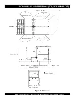
Page 26: ...PAGE 26 DCA 100SSJU PARTS AND OPERATION MANUAL STD REV 2 05 03 01 DCA 100SSJU DIMENSIONS TOP SIDE AND FRONT Figure 7 Dimensions...

Page 27: ...DCA 100SSJU PARTS AND OPERATION MANUAL STD REV 2 05 03 01 PAGE 27 NOTE PAGE...

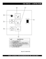
Page 28: ...PAGE 28 DCA 100SSJU PARTS AND OPERATION MANUAL STD REV 2 05 03 01 DCA 100SSJU CONTROL PANEL Figure 8 Control Panel...

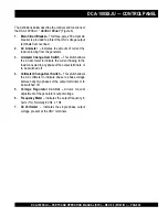
Page 29: ...or 3 Ammeter Change Over Switch This switch allows the AC ammeter to indicate the current flowing to the load connected to any phase of the output terminals or to be switched off 4 Voltmeter Change Ov...

Page 30: ...PAGE 30 DCA 100SSJU PARTS AND OPERATION MANUAL STD REV 2 05 03 01 DCA 100SSJU ENGINE OPERATING PANEL WITH KEY Figure 9 Engine Operating Panel...

Page 31: ...position to start the engine Release the key once the engine has started and it will automatically return to the operating position 11 Oil Pressure Indicator This indicator lets the operator know the...

Page 32: ...PAGE 32 DCA 100SSJU PARTS AND OPERATION MANUAL STD REV 2 05 03 01 DCA 100SSJU ENGINE OPERATING PANEL WITH MPEC Figure 10 Engine Operating Panel...

Page 33: ...empt to crank the engine for 10 seconds before disengaging If the engine does not engage start by the third attempt the engine will be shutdown by the MPEC s Over Crank Protection mode If the engine e...

Page 34: ...gure 13 120Volt Receptacle Two GFCI Duplex Nema 5 20R 120V 20 Amp receptacle is provided on the output terminal This receptacle can be used anytime the generator is in operation The receptacle is cont...

Page 35: ...DCA 100SSJU PARTS AND OPERATION MANUAL STD REV 2 05 03 01 PAGE 35 Legs O and Ground are considered Bonded Grounds NOTE DCA 100SSJU OUTPUTTERMINAL PANEL OVERVIEW FIGURE 16 Output Terminal Panel...

Page 36: ...Voltage Selector Switch press in the red button located on the Voltage Selector Switch and use a pad lock to hold it into this position See figure 17 page 37 Over Current Relay An over current relay i...

Page 37: ...switch to the W U position and the AC ammeter Change over Switch to the U or W position to read the output on the selected leg FIGURE 17 Voltage Selector Switch 240 120V Single Phase Position FIGURE...

Page 38: ...ire Hookup The output terminal panel when suppling three phase 240 volts will provide one circuit available at 241 amps with any twowiresplustheground SeeFigure25below Thevoltage selector switch must...

Page 39: ...ing up the hard wires to the lugs as shown in figure 29 below 480V will be the voltage with the Voltage Regulator Knob turned toward maximum 440 volt will be reached when the Voltage Regulator Knob is...

Page 40: ...oking up the hard wires to the lugs as shown in figure 34 below 240V will be the voltage with the Voltage Regulator Knob turned toward maximum 220 volt will be reached when the Voltage Regulator Knob...

Page 41: ...as shown in figure 38 below use the Voltage Regulator Knob to fine tune to 240V See Figure 37 Single Phase 120 Volt The following connection with the voltage selector switch locked into the single pha...

Page 42: ...which is too long or too small can cause excessive back pressure which will cause the engine to heat excessively and possibly burn the valves CAUTION An electric shock may happen when vibrators are us...

Page 43: ...DCA 100SSJU PARTS AND OPERATION MANUAL STD REV 2 05 03 01 PAGE 43 Figure 40 Typical Generator Grounding Application DCA 100SSJU INSTALLATION...

Page 44: ...e pole 20 amp GFCI circuit breakers are provided to protect the GFCI receptaclesfromoverload Three50amploadcircuitbreakers have also been provided to protect the load side of the generator from overlo...

Page 45: ...TUP Figure 41 Engine Oil Dipstick When checking the engine oil be sure to check if the oil is clean and viscous If the oil is not clean drain the oil by removingtheoildrainplug andrefillwiththespecifi...

Page 46: ...ly clean the radiator fins with compressed air Cleaning inside the machine is dangerous so clean only with the engine turned off and the battery disconnected Air Cleaner Periodic cleaning replacement...

Page 47: ...ount of grease around both battery terminals This will ensure a good connection and will help prevent corrosion around the battery terminals CAUTION Inadequatebatteryconnectionsmaycause poor starting...

Page 48: ...to the generating set s rated output kW multiplied by 0 6 can be used When connecting an electric drill or other power tools pay close attention to the required starting current capacity If wattage i...

Page 49: ...ed fuel immediately Before Starting Generator and Control Panel CAUTION 1 Be sure to disconnect the electrical load and switch the main load and G F C I circuit breakers Figure 44 to the OFF position...

Page 50: ...uipped with a engine throttle lever make sure the lever is pushed in and set to IDLE Figure 50 9 Once the engine is warm and the engine is running properly pull and turn the lever to RUN Figure 52 Fig...

Page 51: ...the specified frequency tolerance use the voltage adjustment control knob Figure 58 to increase or decrease the desired voltage A 0 40 60 75 20 Figure 59 Ammeter No Load 15 The ammeter Figure 59 will...

Page 52: ...UTO mode remember the generator can start up at any time without warning NEVER attempt to perform any maintenance when the generator is in the auto mode 3 Continue to follow the steps outline in the m...

Page 53: ...5 Turn the Auto Off Reset Manual switch from the MPEC to OFF Reset position Figure 69 7 Remove the load from the UNV terminal strip Figure 66 Main GFCI and Load circuit breakers Figure 67 Engine Spee...

Page 54: ...ant Refer to the Engine Instruction Manual Air Cleaner Every50hours Removeaircleanerelementandcleanheavy duty paper element with kerosene or foam element with liquid detergent and hot water Wrap foam...

Page 55: ...X r e t l i F r i A n a e l C X k n a T l e u F f o m o t t o B n i a r D X e d i s t u O d n a e d i s n I t i n U n a e l C X r e t l i F l e u F e g n a h C 2 X n o i t c e t o r P t n a l o o C k...

Page 56: ...h t i w l e u F l e u f d e i f i c e p s e h t e s U n o i t c e j n i e s o o l o t e u d k a e l l e u F t u n g n i n i a t e r e p i p t u n n e t h g i T g n i m i t n o i t c e j n i t c e r r...

Page 57: ...i f i c e p s e h t o t e c u d e R r o n r o w r e n i l d n a g n i r n o t s i P k c u t s e c a l p e r r o r i a p e R g n i m i t n o i t c e j n i t c e r r o c n I t s u j d A n o i s s e r p...

Page 58: ...v e c a l p e R g n i r i w d e t c e n n o c s i D g n i r i w r i a p e r d n a k c e h C e r u t a m r a n i t i u c r i c t r o h s r e y a L g n i d n i w e r u t a m r a e c a l p e R r e w o p...

Page 59: ...o t a i d a r r i a p e r n a e l C n e p o s r o o D s r o o d e s o l C g n i k a e l t s u a h x E t r a p y t l u a f r o s t e k s a g r i a p e r e c a l p e R d e d a o l r e v o g n i e b r o...

Page 60: ...ar part is used Model Number Where indicated this shows that the corresponding part is utilized only with this specific model number or model number variant Items Found In the Items Number Column All...

Page 61: ...y P N Description 1 0601808814 CIRCUIT BREAKER 1 0601820671 AUTOMATICVOLTAGE REGULATOR 1 0601840073 RHEOSTATVOLTAGE REGULATOR 1 0601840121 KNOB RHEOSTAT 1 M3310500003 RADIATOR HOSE 1 M3310500103 RADIA...

Page 62: ...PAGE 62 DCA 100SSJU PARTS AND OPERATION MANUAL STD REV 2 05 03 01 DCA 100SSJU GENERATOR ASSY GENERATOR ASSY...

Page 63: ...LT 4 S 26 7 0042610000 LOCK WASHER 4 8 0041210000 PLAIN WASHER 4 9 0010110035 HEX HEAD BOLT 6 10 0040010000 LOCK WASHER 6 11 0041210000 PLAIN WASHER 6 12 8101310014 COVER BEARING 1 13 8131312014 GASKE...

Page 64: ...PAGE 64 DCA 100SSJU PARTS AND OPERATION MANUAL STD REV 2 05 03 01 DCA 100SSJU CONTROL BOX ASSY CONTROL BOX ASSY...

Page 65: ...CURRENTTRANSFORMER 3 814 943 200 5A 9 0027106015 MACHINE SCREW 6 10 0601820845 OVER CURRENT RELAY 1 LR2D1308 11 0601820846 OVER CURRENT RELAY 1 LA7D1064 12 M1260600004 FITTING BRACKET 1 S N7400001TO 7...

Page 66: ...PAGE 66 DCA 100SSJU PARTS AND OPERATION MANUAL STD REV 2 05 03 01 DCA 100SSJU CONTROL BOX ASSY CONTROL BOX ASSY...

Page 67: ...TO 7400205 AND 7400296 0027105020 MACHINE SCREW 1 S N7400206TO 7400295 42 0602200478 EMERGENCY RELAY 1 10701 60602 3 S N7400001TO 7400295 43 0027105040 MACHINE SCREW 2 S N7400001TO 7400295 44 06022025...

Page 68: ...PAGE 68 DCA 100SSJU PARTS AND OPERATION MANUAL STD REV 2 05 03 01 DCA 100SSJU ENGINE AND RADIATOR ASSY ENGINE AND RADIATOR ASSY...

Page 69: ...00204 RADIATOR BRACKET 1 S N7400001 TO 7400205 17 M3310200404 RADIATOR BRACKET 1 S N7400001 TO 7400205 18 0013006008 HEX HEAD BOLT 8 S N7400001 TO 7400205 19 030206150 LOCK WASHER 8 REPLACES 004300600...

Page 70: ...PAGE 70 DCA 100SSJU PARTS AND OPERATION MANUAL STD REV 2 05 03 01 DCA 100SSJU ENGINE AND RADIATOR ASSY ENGINE AND RADIATOR ASSY...

Page 71: ...400001 TO 7400175 0602202592 RELAY 1 AT141011 S N7400176 57 0017105015 HEX HEAD BOLT 1 S N7400001 TO 7400175 011808015 MACHINE SCREW 2 REPLACES 0027106015 S N7400176 58 M3313100004 RADIATOR COVER 1 S...

Page 72: ...PAGE 72 DCA 100SSJU PARTS AND OPERATION MANUAL STD REV 2 05 03 01 S N 700001TO 7400295 S N 7400296 ENGINE OPERATING PANEL ASSY DCA 100SSJU ENGINE OPERATING PANEL ASSY...

Page 73: ...1481 KEY STARTER SWITCH 1 S N7400001 TO 7400295 0602100028 SET NUT 1 JOHN DEERE R44342 S N7400001 TO 7400295 0602100029 SET WASHER 1 JOHN DEERE A4827R S N7400001 TO 7400295 17 0601831594 COLD STARTING...

Page 74: ...PAGE 74 DCA 100SSJU PARTS AND OPERATION MANUAL STD REV 2 05 03 01 OUTPUT TERMINAL ASSY DCA 100SSJU OUTPUTTERMINAL ASSY...

Page 75: ...00004 SUPPORTER CABLE OUTLET COVER 1 REPLACES M2236400004 17 0016906020 HEX HEAD BOLT 6 18 0601808803 CIRCUIT BREAKER 2 QOU 120B 1P 20A 19 0601808804 CIRCUIT BREAKER 3 QOU 250B 2P 50A 20 M1260700304 B...

Page 76: ...PAGE 76 DCA 100SSJU PARTS AND OPERATION MANUAL STD REV 2 05 03 01 DCA 100SSJU BATTERY ASSY BATTERY ASSY...

Page 77: ...TERY SHEET 1 3 M9103000504 BATTERY BAND 1 4 0602220921 BATTERY BOLT SET 2 5 0040006000 LOCKWASHER 2 6 M3346900004 BATTERY CABLE 1 7 M3346900104 BATTERY CABLE 1 8 CABLE 1 9 0017112025 HEX HEAD BOLT 1 0...

Page 78: ...PAGE 78 DCA 100SSJU PARTS AND OPERATION MANUAL STD REV 2 05 03 01 DCA 100SSJU MUFFLER ASSY BATTERY ASSY...

Page 79: ...FFLER 1 27299N S N74000054 2 012210025 HEX HEAD BOLT 4 REPLACES 0016910025 3 M3333000303 EXHAUST PIPE 1 4 0602325066 CLAMP 1 M001432 5 M3333200004 GASKET 1 6 00017110040 HEX HEAD BOLT 4 7 M33330400304...

Page 80: ...PAGE 80 DCA 100SSJU PARTS AND OPERATION MANUAL STD REV 2 05 03 01 DCA 100SSJU FUELTANK ASSY FUEL TANK ASSY...

Page 81: ...S 0041208000 S N7400001TO 7400026 6 0222100660 RUBBER SHEET 2 7 1502025103C DRAIN JOINT 1 REPLACES M9200000003 8 M9200200004 DRAIN BOLT 1 9 0150000018 O RING 1 A P18 10 011206020 HEX HEAD BOLT 2 REPLA...

Page 82: ...SURE ASSY DCA 100SSJU ENCLOSURE ASSY ADD THE FOLLOWING DIGITS AFTER THE PART NUMBER WHEN ORDERING ANY PAINTED PANEL TO INDICATE COLOR OF UNIT 1 ORANGE 2 WHITE 3 SPECTRUM GRAY 4 SUNBELT GREEN 5 BLACK 6...

Page 83: ...00296 11 012210025 HEX HEAD BOLT 4 REPLACES 0016910025 12 M3443300203 REAR COVER 1 13 M3443300303 DUCT REAR COVER 1 M3493300303 ACOUSTIC SHEET 1 14 0207006000 HEX NUT 12 15 011008020 HEX HEAD BOLT 10...

Page 84: ...PAGE 84 DCA 100SSJU PARTS AND OPERATION MANUAL STD REV 2 05 03 01 ENCLOSURE ASSY DCA 100SSJU ENCLOSURE ASSY...

Page 85: ...M3453300203 DUCT 1 M3493401204 ACOUSTIC SHEET 1 41 0207006000 HEX NUT 25 42 89114000002 DOOR HANDLE ASSY 4 REPLACES M9113000002 43 0027106016 MACHINE SCREW 16 REPLACES 0021806015 020106050 HEX NUT 16...

Page 86: ...PAGE 86 DCA 100SSJU PARTS AND OPERATION MANUAL STD REV 2 05 03 01 DCA 100SSJU RUBBER SEAL ASSY RUBBER SEAL ASSY...

Page 87: ...0228900955 RUBBER SEAL 4 6 0228900470 RUBBER SEAL 2 7 0229201100 RUBBER SEAL 4 8 0229201040 RUBBER SEAL 1 9 0228800970 RUBBER SEAL 2 10 0228800590 RUBBER SEAL 1 11 0228800630 RUBBER SEAL 1 12 0228100...

Page 88: ...PAGE 88 DCA 100SSJU PARTS AND OPERATION MANUAL STD REV 2 05 03 01 DCA 100SSJU DECALS DECAL ASSY...

Page 89: ...20000 17 M9510100004 DECAL CAUTION 1 M91010000 18 M9510200002 DECAL MQ 1 M91020000 19 M9520000004 DECAL GROUND 1 M92000000 20 M9520000104 DECAL AMMETER CHANGE OVER SWITCH 1 M92000010 21 M9520000204 DE...

Page 90: ...t be liable here under for damagesinexcessofthepurchasepriceofthe item with respect to which damages are claimed and in no event shall Multiquip be liable for loss of profit or good will or for any ot...

Page 91: ...DCA 100SSJU PARTS AND OPERATION MANUAL STD REV 2 05 03 01 PAGE 91 NOTE PAGE...

Page 92: ...927 FAX 310 638 8046 E mail mq multiquip com www multiquip com PARTS AND OPERATION MANUAL HERE S HOW TO GET HELP PLEASE HAVE THE MODEL AND SERIAL NUMBER ON HANDWHEN CALLING PARTS DEPARTMENT 800 427 12...

Reviews: