background image

User Manual


33 


Enter:  Triggers  when  the  trigger  signal  enters  the 
specified trigger level range.   
Exit:  Triggers  when  the  trigger  signal  exits  the 
specified trigger level range. 
Time:  Specify  the  hold  time  of  the  input  signal  after 
entering  the  specified  trigger  level.  The  oscilloscope 
triggers when the accumulated hold time is greater than 
the windows time. Available range is 30ns-10s, default 
100ns. 

Mode 


Holdoff 

Auto 

Normal 

Single 

Holdoff 


Reset 

Acquire waveform even no trigger occurred 
Acquire waveform when trigger occurred 
When trigger occurs, acquire one waveform then stop 
100 ns - 10 s, adjust 

M

 rotary control to set time 

interval before another trigger occur, press 


panel button to move cursor to choose which digit to be 
set. 
Set Holdoff time as 100 ns 

7.Timeout Trigger 

The oscilloscope triggers when the time interval from when the rising edge (or the 
falling edge) passes through the trigger level to when the neighbouring falling edge 
(or the rising edge) passes through the trigger level is greater than the timeout time 
set.   
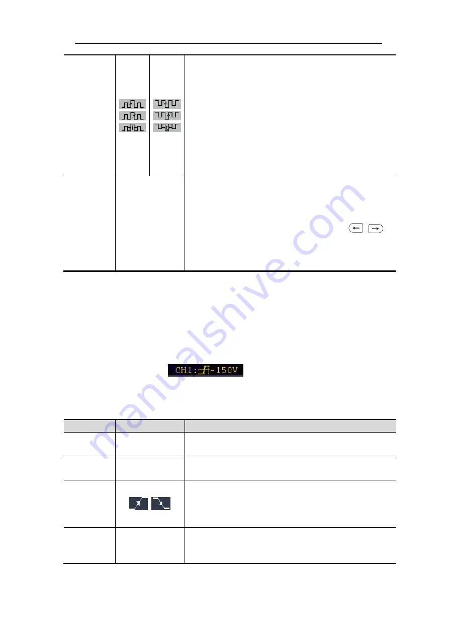
In Timeout Trigger mode, the trigger setting information is displayed on bottom right 

of the screen, for example,


indicates that trigger type is Timeout, 

trigger source is CH1, edge is positive, 0.00mV is up level or low level threshold. 


Timeout Trigger menu

 list: 

MENU 

SETTING 

INSTRUCTION 

Single 

Mode 

Timeout 

Set vertical channel trigger type as Timeout trigger. 

Source 

CH1 
CH2 

Select CH1 as the trigger source. 
Select CH2 as the trigger source. 

Edge 

Edge


Start timing when the rising edge of the input signal 
passes through the trigger level.   
Start timing when the falling edge of the input signal 
passes through the trigger level. 

Configure 

Idle Time 

Set idle time. Idle time means the minimum time of idle 
clock  before  searching  data  that  can  meet  trigger 
conditions. Available range is 30ns-10s, default 100ns. 

Summary of Contents for MP720024

Page 1: ...i Digital Storage Oscilloscope 100MHz Model MP720024...

Page 2: ...Self calibration 13 Introduction to the Vertical System 14 Introduction to the Horizontal System 15 Introduction to the Trigger System 15 4 Advanced User Guidebook 17 How to Set the Vertical System 1...

Page 3: ...ation with PC 80 Using USB Port 80 Using LAN Port 81 Connect directly 81 Connect through a router 83 6 Demonstration 85 Example 1 Measurement a Simple Signal 85 Example 2 Gain of a Amplifier in a Mete...

Page 4: ...ed The product must be grounded properly before any connection with its input or output terminal When powered by AC power it is not allowed to measure AC power source directly because the testing grou...

Page 5: ...le potentially Caution It indicates a potential damage to the instrument or other property might occur Safety Symbols Symbols on the product The following symbol may appear on the product Hazardous Vo...

Page 6: ...ke note of below items Only use accessory insulated voltage probes and test lead Check the accessories such as probe before use and replace it if there are any damages Remove probes test leads and oth...

Page 7: ...o the user interface How to implement the general inspection How to implement the function inspection How to make a probe compensation How to set the probe attenuation coefficient How to use the probe...

Page 8: ...can set the different options for the current menu The other buttons are function buttons through which you can enter different function menus or obtain a specific function application directly 8 2 5...

Page 9: ...ight menu item Select the bottom menu item Remove the left and right menu Figure 3 2 Menu Buttons Rear Panel 9 8 7 6 11 1 2 5 3 4 10 Figure 3 3 Rear Panel 1 Handle 2 Air vents 3 AC power input jack 4...

Page 10: ...Fail W REC Waveform Record 3 Trigger control area with 2 buttons and 1 rotary control The Trigger Level rotary control is to adjust trigger voltage Other 2 buttons refer to trigger system setting 4 H...

Page 11: ...the left and right User Interface Introduction 1 3 15 10 23 20 6 7 8 9 12 13 16 17 18 22 24 5 14 21 2 4 19 11 4 12 Figure 3 5 Illustrative Drawing of Display Interfaces 1 Waveform Display Area 2 Run...

Page 12: ...lue TR the Cycle RMS CR the Cursor RMS WP the Screen Duty RP the Phase PC the Pulse count PC the Pulse count E the Rise edge count E the Fall edge count AR the Area CA the Cycle area 15 The icon shows...

Page 13: ...pection Make a fast function check to verify the normal operation of the instrument according to the following steps 1 Connect the power cord to a power source Long press the button on the bottom left...

Page 14: ...at of the switch in the probe as 10X see How to Set the Probe Attenuation Coefficient on P12 and connect the probe with the CH1 channel If a probe hook tip is used ensure that it keeps in close touch...

Page 15: ...ect the proper value corresponding to the probe This setting will be valid all the time before it is changed again Caution The default attenuation coefficient of the probe on the instrument is preset...

Page 16: ...arning To avoid electric shock always keep your finger behind the safety guard ring of the probe during the operation To protect you from suffering from the electric shock do not touch any metal part...

Page 17: ...DC component would be filtered out This mode helps you display the AC component of the signal with a higher sensitivity Vertical offset back to 0 shortcut key Turn the Vertical Position rotary control...

Page 18: ...form window The Horizontal Position rotary control is used to control the triggering displacement of the signal or for other special applications If it is applied to triggering the displacement it can...

Page 19: ...ntrol the trigger indicator in the screen will move up and down With the movement of the trigger indicator it can be observed that the trigger level value displayed in the screen changes accordingly N...

Page 20: ...book This chapter will deal with the following topics mainly How to Set the Vertical System How to Set the Horizontal System How to Set the Trigger Decoding System How to Implement the Sampling Setup...

Page 21: ...ting Description Coupling DC AC GROUND Pass both AC and DC components of the input signal Block the DC component of the input signal Disconnect the input signal Inverted ON OFF Display inverted wavefo...

Page 22: ...shown as follows 1 Push the CH1 button to show CH1 SETUP menu 2 Select Probe in the bottom menu In the right menu set MeasCurr as YES the A V radio menu will appear below Select it turn the M rotary...

Page 23: ...the signal source of the factor2 Vertical div Turn the M rotary control to adjust the vertical position of the Math waveform Vertical V div Turn the M rotary control to adjust the vertical division of...

Page 24: ...d Triangular Hanning Hamming Blackman Select window for digital filter cut off fre or upper down Turn the M rotary control to set cut off frequency Vertical div Turn the M rotary control to adjust the...

Page 25: ...R in the bottom menu 3 In the right menu select channel as CH1 or CH2 4 In the right menu select type select the desired filter type 5 In the right menu select window select the desired window 6 When...

Page 26: ...in front of the horizontal position value the upper one turn the M rotary control to adjust the horizontal position of FFT waveform then select to make the symbol in front of the time base value below...

Page 27: ...mming Recommend to use for Sine periodic and narrow band random noise Transients or bursts where the signal levels before and after the event are significantly different Kaiser The frequency resolutio...

Page 28: ...ion to the relation between the frequency being sampled and measured Use Vertical Position and Scale Rotary controls 1 The Vertical Position rotary control is used to adjust the vertical positions of...

Page 29: ...Time base of Zoom window Selected portion Horizontal position of Zoom window Zoom Window In normal mode the Horizontal Position and Horizontal Scale rotary controls are used to adjust the horizontal...

Page 30: ...rigger menus are described respectively as follows Single Trigger Single trigger has eight types edge trigger video trigger slope trigger pulse trigger runt trigger windows trigger timeout trigger and...

Page 31: ...gnal only high frequency component pass LF menu is only for certain models Slope Trigger on rising edge Trigger on falling edge Mode Holdoff Auto Normal Single Holdoff Reset Acquire waveform even no t...

Page 32: ...f Auto Acquire waveform even no trigger occurred 3 Slope Trigger Slope trigger sets the oscilloscope as the positive negative slope trigger within the specified time In Slope Trigger mode the trigger...

Page 33: ...occurs according to the width of pulse The abnormal signals can be detected through setting up the pulse width condition In Pulse Width Trigger mode the trigger setting information is displayed on bo...

Page 34: ...r setting information is displayed on bottom right of the screen for example indicates that trigger type is runt trigger source is CH1 polarity is positive 0 00mV is the differential between up level...

Page 35: ...d low trigger level the oscilloscope triggers when the input signal passes through the high trigger level or the low trigger level In Windows Trigger mode the trigger setting information is displayed...

Page 36: ...terval from when the rising edge or the falling edge passes through the trigger level to when the neighbouring falling edge or the rising edge passes through the trigger level is greater than the time...

Page 37: ...below the oscilloscope should trigger on the second falling edge after the specified idle time and the idle time should be set to P1 P2 P3 P4 Idle Time M Wherein M P1 P2 P3 and P4 are positive or nega...

Page 38: ...ther trigger occur press panel button move cursor to choose which digit to be set Set Holdoff time as 100 ns Alternate Trigger Trigger mode Edge Trigger signal comes from two vertical channels when al...

Page 39: ...ime Out Mod Goes True Trigger when condition turns True from False Trigger when condition turns False from True Trigger when the time of true condition is more than the set time Trigger when the time...

Page 40: ...start frame of position After choosing this condition press Configure to enter detailed settings Error Trigger when error frame is detected After choosing this condition press Configure to enter detai...

Page 41: ...ission data is determined by SDA As shown in below figure oscilloscope can trigger on the start restart stop ack lost specific device address or data value also device address and data value at the sa...

Page 42: ...lect the data bit ranges from 0 to byte length 8 1 Set data to be H L or X H or L Set all the data bits to be the specified value in Data Curr entB it Data All Bits Addr Data Trigger when Address and...

Page 43: ...or X H or L Set all the data bits to be the specified value in Data Data Bits Current Bit Data All Bits Mode Holdoff Auto Normal Single Acquire waveform even no trigger occurred Acquire waveform when...

Page 44: ...arest value in Common Baud and then adjust it in this menu Condition Start Trigger on the start frame of the data frame Type Type Bottom menu Data Trigger on the selected frame Remote Error Overload I...

Page 45: ...s of the signal When the parameters are set correctly the information carried by the signal will be displayed Tip If there are repetitive menu items in both trigger menu and decoding menu you can set...

Page 46: ...acteristics of the signal trigger the signal correctly and obtain stable display Refer to I2C Trigger on page 38 4 Push the Decode button on the front panel Select bus type as I2C set parameters based...

Page 47: ...as SPI set parameters based on the characteristics of the signal trigger the signal correctly and obtain stable display Refer to SPI Trigger on page 39 4 Push the Decode button on the front panel Sel...

Page 48: ...ument save the event table data in a csv spreadsheet formatted file on the external USB storage device 4 CAN Decoding To decode CAN signal 1 Connect the CAN signal to the Signal Input Channel of the o...

Page 49: ...ecoding menu list MENU SETTING INSTRUCTION Bus Type CAN Set bus type of decoding as CAN Display Format Binary Decimal Hex ASCII Set the display format of the bus EventTable ON OFF Select ON to display...

Page 50: ...12 bit When the sample rate 250MS s ADC resolution is set to 12 bit by default When the sample rate 250MS s and both channels are turned on ADC resolution is set to 8 bit by default When the sample r...

Page 51: ...User Manual 48 Sine x x interpolation Linear interpolation...

Page 52: ...f previous acquisitions from the display The oscilloscope will start to accumulate acquisitions again XY Format This format is only applicable to Channel 1 and Channel 2 After the XY display format is...

Page 53: ...full screen select Full Screen as ON in the right menu Counter It is a 6 digit single channel counter The counter can only measure the frequency of the triggering channel The frequency range is from 2...

Page 54: ...urrent internal object address or into USB storage as a single file Object Show Object 0 49 Choose the address which the waveform is saved to or recall from Show ON OFF Recall or close the waveform st...

Page 55: ...rmat Save and Recall the Waveform The oscilloscope can store 50 waveforms which can be displayed with the current waveform at the same time The stored waveform called out can not be adjusted In order...

Page 56: ...orage of the save menu is set as External you should install the USB disk Please refer to the contents below to install the USB disk and name the file to be saved Save the current screen image The scr...

Page 57: ...1 Connect the USB disk to the computer 2 Right click Computer Manage to enter Computer Management interface 3 Click Disk Management menu and information about the USB disk will display on the right si...

Page 58: ...allocation unit size 4096 after formatting Use Minitool Partition Wizard to format Download URL http www partitionwizard com free partition manager html Tip There are many tools for the USB disk forma...

Page 59: ...ush keyboard F5 and information about the USB disk will display on the right side with red mark 1 and 2 Figure 4 6 Reload Disk 4 Right click 1 or 2 red mark area choose Format Figure 4 7 Choose format...

Page 60: ...4 11 Format successfully How to Record Playback Waveforms Wave Record function can record the input current wave You can set the interval between recorded frames in the range of 10 ms 10 s The max fra...

Page 61: ...be recorded If a Channel is turned off while recording the waveform of the channel is invalid in the playback mode Playback Play back the wave recorded or saved Playback menu shows as follows Menu Se...

Page 62: ...mode select Operate as Play 10 To save the wave recorded select Mode in the bottom menu select Storage in the right menu Select FrameSet in the bottom menu to set the range of frames to store select S...

Page 63: ...in the right menu 6 Select FrameSet in the bottom menu set End frame and Interval in the right menu If you want to record wave to external infinitely select Infinity in the right menu the End frame wi...

Page 64: ...ion To clone waveform and save to the internal USB memory 1 Push Save button 2 Select Type in the bottom menu in the left menu turn the M rotary control to select Clone 3 Select Source in the bottom m...

Page 65: ...rm will be saved onto the USB memory device as a file with the ota suffix Data format description of OTA waveform file If the source is CH1 or CH2 OTA file consists of two parts the file header and th...

Page 66: ...mine the data type char short int or int based on the BYTE parameter The valid range is determined by the ADCB parameter e g the valid range for 8 bit ADC is 127 to 127 How to Implement the Auxiliary...

Page 67: ...r exceeds 5 the self calibration procedure should be executed to obtain the highest level of accuracy Before executing the self calibration procedure disconnect all probes or wires from the input conn...

Page 68: ...tton select Function in the bottom menu select Pass fail in the left menu 2 Enable switch on Select Operate in the bottom menu select Enable in the right menu as ON 3 Create rule Select Rule in the bo...

Page 69: ...n running the number of Pass Fail will increase from the former number not from zero 5 When the waveform playback mode is on Pass Fail is used to test the played back waveform specially Output Push th...

Page 70: ...Top Base Amplitude Overshoot Preshoot Rise Time Fall Time PulseWidth PulseWidth Duty Cycle Duty Cycle Delay A B Delay A B Cycle RMS Cursor RMS Screen Duty Phase PulseCount PulseCount RiseEdgeCnt FallE...

Page 71: ...right menu select CH1 in the Source menu item 4 In the left Type menu turn the M rotary control to select Period 5 In the right menu select Add The period type is added 6 In the left Type menu turn t...

Page 72: ...ul for square pulse waveforms Vamp Voltage between Vtop and Vbase of a waveform OverShoot Defined as Vmax Vtop Vamp useful for square and pulse waveforms PreShoot Defined as Vmin Vbase Vamp useful for...

Page 73: ...channels at the rising edge Delay A B The delay between the two channels at the falling edge Screen Duty Defines as the width of the positive pulse Entire period Phase Compare the rising edge of CH1 a...

Page 74: ...ursors Push the Cursor button to turn cursors on and display the cursor menu Push it again to turn cursors off The Cursor Measurement for normal mode The description of the cursor menu is shown as the...

Page 75: ...readout 4 In the bottom menu select Line Type as Time to make the vertical cursors active If the Line in the bottom menu is select as a turn the M rotary control to move line a to the right or left I...

Page 76: ...sponding measurement cursor and menu AutoCursr The horizontal cursors are set as the intersections of the vertical cursors and the waveform Line Type Freq Vamp or Freq Phase type Freq Makes the vertic...

Page 77: ...wo blue dotted lines displayed along the horizontal direction of the screen two blue dotted lines displayed along the vertical direction of the screen Cursor measure window at the left bottom of the s...

Page 78: ...ting Instruction Autoscale ON OFF Turn on Autoscale Turn off Autoscale Mode Follow up and adjust both vertical and horizontal settings Follow up and only adjust horizontal scale Follow up and only adj...

Page 79: ...coupling with AUTO triggering 5 At the mode of Autoscale if adjust the vertical position voltage division trigger level or time scale of CH1 or CH2 the oscilloscope will turn off Autoscale function To...

Page 80: ...re set functions to the incoming signal and display the best possible viewing waveform of the signal and also works out some measurements for user as well The details of functions applied to the signa...

Page 81: ...ay the falling edge of square waveform Cancel Autoset Go back to display the upper menu and waveform information Note The Autoset function requires that the frequency of signal should be no lower than...

Page 82: ...s the follows 1 Connect the printer to the USB Device port on the rear panel of the oscilloscope Note The USB Device port supports PictBridge compatible printers 2 Push the Utility button select Funct...

Page 83: ...hoose from Using USB Port 1 Connection Use a USB data cable to connect the USB Device port in the right panel of the Oscilloscope to the USB port of a PC 2 Install the driver Run the Oscilloscope comm...

Page 84: ...et the IP address to 192 168 1 71 Figure 5 2 Set the network parameters of the computer 3 Set the network parameters of the OWON Oscilloscope Software Run the software on the computer choose the Ports...

Page 85: ...t in the left menu In the bottom menu set the Type item as LAN and select Set In the right menu set IP and Port to the same value as the Ports settings in the software in step 3 Select Save set in the...

Page 86: ...to the router Here we set the IP address to 192 168 1 71 Subnet mask is 255 255 255 0 Default gateway is 192 168 1 1 Figure 5 5 Set the network parameters of the computer 3 Set the network parameters...

Page 87: ...menu set the Type item as LAN and select Set In the right menu set IP and Port to the same value as the Ports settings in the software in step 3 The Netgate and Net mask should be set according to th...

Page 88: ...eform optimized based on which you can further regulate the vertical and horizontal divisions till the waveform meets your requirement 2 Perform Automatic Measurement The oscilloscope can measure most...

Page 89: ...nnel to the output end Operation Steps 1 Push the Autoset button and the oscilloscope will automatically adjust the waveforms of the two channels into the proper display state 2 Push the Measure butto...

Page 90: ...losest trigger level and trigger type this helps user to make few small adjustments to achieve a proper trigger level and mode Here is how we achieve this The operation steps are as follows 1 Set the...

Page 91: ...sh the Run Stop button and wait a trigger Once there is a burr occurring the instrument will trigger automatically and record the waveform during the period around the trigger time By turning the Hori...

Page 92: ...el as lower as possible this would enable user to have more details about the signal The Average function offered by our Oscilloscope can help you to achieve this Here are the steps for how to enable...

Page 93: ...rate according to the following steps 1 Set the probe menu attenuation coefficient for 10X and that of the switch in the probe for 10X see How to Set the Probe Attenuation Coefficient on P12 2 Connect...

Page 94: ...he determined phase difference angel should be in the I and IV quadrants that is in the range of 0 2 or 3 2 2 If the principal axis of the ellipse is in the II and IV quadrants the determined phase di...

Page 95: ...the bottom menu Select CH1 in the right menu 5 Select Modu in the bottom menu Select NTSC in the right menu 6 Select Sync in the bottom menu Select Field in the right menu 7 Turn the Vertical Scale Ve...

Page 96: ...robe Attenuation Coefficient on P12 4 There is a waveform displayed but it is not stable Check whether the Source item in the TRIG MODE menu is in conformity with the signal channel used in the practi...

Page 97: ...ith the word Typical Performance Characteristics Instruction Bandwidth 100 MHz Vertical Resolution A D 12 bits Channel 2 1 External Waveform Refresh Rate 55 000 wfms s Acquisition Mode Normal Peak det...

Page 98: ...3 5 ns DC gain accuracy 1 mV 3 2 mV 2 5 mV 1 5 DC accuracy average Delta Volts between any two averages of 16 waveforms acquired with the same scope setup and ambient conditions V 3 rdg 0 05 div Wavef...

Page 99: ...to Record length and time base Trigger Holdoff range 100 ns 10 s 50 level setting typical Input signal frequency 50 Hz Edge trigger slope Rising Falling Video Trigger Modulation Support standard NTSC...

Page 100: ...Data Bits 5 bit 6 bit 7 bit 8 bit I2C Trigger Trigger Condition Start Restart Stop ACK Lost Address Data Addr Data Address Bits 7 bit 8 bit 10 bit Address Range 0 to 127 0 to 255 0 to 1023 Byte Lengt...

Page 101: ...Frequency Typical Square wave of 1 KHz Power Mains Voltage 100V 240 VACRMS 50 60 Hz CAT Power Consumption 15 W Fuse 2 A T class 250 V Environment Temperature Working temperature 0 40 Storage temperatu...

Page 102: ...User Manual 99 9 Appendix Appendix A Enclosure The accessories subject to final delivery Standard Accessories Power Cord CD Rom Quick Guide USB Cable Probe Probe Adjust Options Q9 Soft Bag...

Page 103: ...off status by soft cloth that is lightly moistened Itis allowed to be cleaned by soft detergent or fresh water Do not use any abrasive chemical detergent to avoid the instrument or the probe being dam...

Reviews: