background image


Configuring TRAIL-Control 

Configuring the speed sensor 


30 

V2.20160912 

30322332-02-EN 


NOTICE 

Imprecise calibration 

The speed cannot be precisely determined with an incorrectly calibrated wheel sensor. 
As a result, all the calculations of the applied area, the traveled distance and the volume applied will 
be highly imprecise. 

◦  Calibrate the wheel sensor very precisely. 


Determining the pulses per 100 meters 

When calibrating the wheel sensor with the 100m method, you determine the number of pulses 
received by the sensor over a distance of 100 meters. 

In order for the system to function correctly, the wheel sensor must receive at least 250 pulses over a 
distance of 100 meters. 

To increase the number of pulses, you must install additional magnets opposite of the wheel sensor. 

If you know the number of pulses for the wheel sensor, you can also enter this number manually. 


  Wheel sensor is installed. 


  All wheel sensor magnets are fully functional. 


  A distance of 100m has been measured and marked. The distance must correspond to the field 

conditions. It should therefore lead over a meadow or a field. 


  The tractor with connected implement is operational for a 100m drive and is positioned at the 

start of the marked distance. 

1. 

Ensure that all prerequisites have been fulfilled. 

2. 

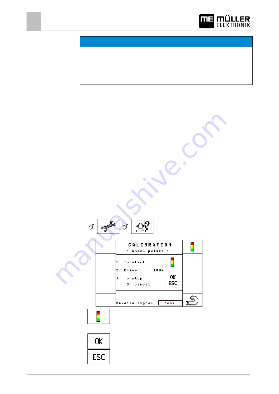
Switch to the "CALIBRATION – wheel pulses" screen: 


  The following screen appears: 


3. 

 - Start calibration. 

4. 

The following function icons appear: 

 - Stop calibration. 

 - Abort calibration. 

6.4.2 

Procedure 

Summary of Contents for ISOBUS TRAIL-Control

Page 1: ...Operators Manual ISOBUS TRAIL Control Version V2 20160912 30322332 02 EN Read and follow these operating instructions Keep these operating instructions in a safe place for later reference...

Page 2: ...322332 02 EN As of software version 2x7g Original language German M ller Elektronik GmbH Co KG Franz Kleine Stra e 18 33154 Salzkotten Germany Phone 49 0 5258 9834 0 Fax 49 0 5258 9834 90 Email info m...

Page 3: ...4 4 1 1 Mounting the bracket for the gyroscope 14 4 1 2 Using the gyroscope 15 4 2 Checking the installation position of sensors 15 5 Operating the system 17 5 1 Switching TRAIL Control on and off 17...

Page 4: ...ng 31 6 5 1 Centering when exceeding the maximum speed 32 6 5 2 Centering when switching to manual mode 32 6 5 3 Centering when tapping the centering icon 33 6 6 Configuring automatisms when driving i...

Page 5: ...bility of the unit Modifications are considered unauthorized if they are not described in the product documentation Keep children away from the implement and from the job computer Hazard Area The haza...

Page 6: ...Instructions are composed in accordance with the following pattern WARNING This signal word identifies medium risk hazards which could potentially cause death or serious physical injury if not avoide...

Page 7: ...steering They still both have the same function In the manual we use the icons depicting a drawbar For each of these icons there is a corresponding icon depicting an axle with wheels You can find an...

Page 8: ...22332 02 EN Type of depiction Meaning This will happen when you perform an action Result of an operating instruction This will happen when you have completed all steps Requirements In the event that a...

Page 9: ...ese systems steer the steering axle of the trailed implement to the left or right to influence the course of the trailed implement The following requirements must be met for TRAIL Control to work Mini...

Page 10: ...irection of the tractor ISOBUS cable with plug Cable from the ISOBUS job computer to the ISOBUS socket on the tractor ISOBUS job computer Control unit that is responsible for system operation Boom unf...

Page 11: ...ork screen when steering in automatic mode The tractor drives to the right the trailed implement is steered to the left By looking at the displayed position of the drawbar stub axle you can see whethe...

Page 12: ...is folded for driving on roads Automatic mode is not possible A locking device is activated Drawbar locking device or ladder sensor TRAIL Control is locked The hydraulic valve is not being controlled...

Page 13: ...ption Rating plate 3 30322332 02 EN V2 20160912 13 Abbreviation Meaning M ller Elektronik item number Operating voltage The product may only be connected to voltages within this range Software version...

Page 14: ...he bracket on the tractor is used for fastening the gyroscope to the tractor for the duration of work in the field 1 Determine the position for mounting the bracket on the tractor The bracket must be...

Page 15: ...s allows you to check whether selected sensors are properly installed Sensor voltages Sensor type Position during measurement Correct voltage Angle sensor Center position The drawbar or wheels of the...

Page 16: ...lation position of sensors 16 V2 20160912 30322332 02 EN 1 Switch to the TRAIL Control screen The TRAIL Control screen appears The voltages appear in the bottom half of the screen For the speed sensor...

Page 17: ...unfolded The Boom unfolded sensor if the sensor is installed is activated The drawbar is not mechanically locked The ladder is not extended or unfolded If the ladder sensor is installed 1 Fasten the...

Page 18: ...screen Layout of the work screen 10 If you still have to configure the system Configuring TRAIL Control 23 If the system has already been configured Steering in automatic mode 18 Steering in manual m...

Page 19: ...in reverse depends on several factors If no reverse driving signal 31 is available you can deactivate TRAIL Control or set it to manual mode before driving in reverse As a standard TRAIL Control stop...

Page 20: ...first have to manually adjust the correct position for each slope Afterwards it will be automatically maintained by the system To steer against the slope in automatic mode The trailed implement is equ...

Page 21: ...trailed implement may move with an offset relative to the tractor s tracks This may cause a traffic accident Before you drive on a road Calibrate TRAIL Control Ensure that when driving straight ahead...

Page 22: ...e joystick are assigned as follows Switch between TRAIL Control s manual and automatic mode Switching TRAIL Control on and off Buttons 1 4 are not assigned Steer trailed implement to the left Steer tr...

Page 23: ...ors When the steering starts up abruptly Deviation tolerance 23 When changing tractors Distance between the rear wheel axle of the tractor and the towing hook 23 When changing tractors Calibrate the w...

Page 24: ...aning Starts the calibration of the middle position Starts the calibration of the left limit stop Starts the calibration of the right limit stop Steers the implement to the left Steers the implement t...

Page 25: ...unction icon also appears on the work screen and has the same function there as on this screen Compensation time Enter only for trailed implements with a bang bang valve The greater the value the earl...

Page 26: ...and right positions The job computer calculates all intermediate positions itself To do so the slope sensor must be installed Its position may no longer be changed after this Step 2 Calibrating the hy...

Page 27: ...e calibration is ready 5 Confirm within 3 seconds Calibration is initiated The following message appears Middle position the calibration is running Phase 1 is completed when the message Middle positio...

Page 28: ...he hydraulics of the proportional valve when you use a trailed implement with proportional valve WARNING Danger of injury from trailed implement movement When calibrating the proportional valve the tr...

Page 29: ...alibration The following message appears Hydraulics calibration ready 6 Confirm within 3 seconds The following message appears Hydraulics calibration is running The drawbar now moves slowly to the lef...

Page 30: ...t least 250 pulses over a distance of 100 meters To increase the number of pulses you must install additional magnets opposite of the wheel sensor If you know the number of pulses for the wheel sensor...

Page 31: ...when driving in reverse 33 The following signal sources are possible None The job computer should not expect a reverse driving signal Even if a reverse driving signal is transmitted through the ISOBUS...

Page 32: ...The maximum speed is generally 9 32 mph however it can be increased by the manufacturer in some cases when the construction allows it For activation mark the box near these icons As soon as the maxim...

Page 33: ...ng in reverse Several tractors can send a signal through the ISOBUS to all ISOBUS job computers when the reverse gear is engaged TRAIL Control can then detect a reverse driving signal and react to it...

Page 34: ...d after 8 seconds the centering procedure is aborted Several tractors send a reverse driving signal unexpectedly or without reason even if they are standing still To minimize the risks for the driver...

Page 35: ...g other ECUs 42 pin plug for sensors and actuators Power supply 9 32 V DC Power consumption 110 mA at 13 8V without power output without supply to external sensors Temperature range 20 to 70 C in acco...

Page 36: ......

Page 37: ......

Reviews: