background image


T  H  E     W  O  R  L  D     P  O  W  E  R     I  N     A  N  C  H  O  R  I  N  G     S  Y  S  T  E  M  S 


HFF600S MANUAL 

WWW.MUIR.COM.AU

 Page: 

12 


Rope/Chain Splice. 

 
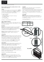
1. To stop rope unravelling, seize rope 400mm(16") from 
end with whipping twine. Unlay strands. 


2. After placing 20mm (3/4") of heat shrink sleeve tubing 
through the last link of chain, pass one strand of rope 

through sleeve and chain from one side and the other two 
strands of rope from the opposite side. (See illustration). 


3. While pulling all three strands tight, shrink the sleeve 
tightly onto the rope using a hairdryer / fan heater or by 
immersing in boiling water. 


4. Remove seizing and complete back splice in normal 
manner for two full tucks. With a hot knife pare down the 

three strands by 1/3 and insert two further tucks. Pare down by another1/3 and finish with two 
tucks. Cut any remaining tails. 


TROUBLE SHOOTING 


Electrical 


1.


Check the battery circuit breaker and ensure the isolating switch is on.  

2.


Check battery is charged up to 12 volts. 

3.


Check that the foot switch plunger is contacting (if fitted) 

4.


Check remote control solenoid is contacting, if this is clicking the problem may be low 
voltage, a faulty solenoid or a wire not properly connected. 

5.


Check wiring between controls, solenoid and motor are in-tact. 


Mechanical 


If the windlass running gear will not turn or operate check the following 


1.


Check that the clutch beside the chain gypsy is tightened to the chain gypsy drive 
using the manual handle supplied (see operating instructions). 


Freefall Mechanism 


1.


Check that the freefall plunger and spring can move freely. 

2.


Ensure that the declutcher pawl is in the correct position and that the grub screws 
holding this in place are tightened. 

Summary of Contents for HFF 600S

Page 1: ...T H E W O R L D P O W E R I N A N C H O R I N G S Y S T E M S HFF600S MANUAL WWW MUIR COM AU Page 1 HFF 600S HORIZONTAL WINDLASS WINDLASS SERIAL NUMBER ...

Page 2: ...T H E W O R L D P O W E R I N A N C H O R I N G S Y S T E M S HFF600S MANUAL WWW MUIR COM AU Page 2 ...

Page 3: ...el 6 Minimum Fall 6 HANDY HINTS 7 ELECTRICAL 7 Circuit breaker must be fitted to ensure warranty 7 Deck Switches 7 Isolating Switch 7 Batteries 7 Rotation 7 OPERATING INSTRUCTIONS 9 Maintenance servicing 10 Line Care Error Bookmark not defined Rope Chain Splice 12 Trouble Shooting 12 ELECTRICAL 12 MECHANICAL 12 Freefall Mechanism 12 DRAWINGS 13 Deck Template Wiring Diagram for 12V DC two wire 400W...

Page 4: ...intervals from the anchor to alert the operator to the anchor position Alternatively an Auto Anchor can be used Under no circumstances should the windlass be operated if it is stalled or overloaded If anchor retrieval is impaired by high wind heavy seas or the anchor is snagged ease the load by either motoring or sailing slowly forward into the wind SAFE OPERATION Ensure that hands feet hair and c...

Page 5: ... an appropriate sealant to the base plate and mounting block if required and carefully tighten the nuts washers onto the threaded studs under the deck Remove excess sealer For Aluminium or Steel hull vessels it is important to insulate the windlass with a non conductive gasket to avoid corrosion This also applies below deck with the mounting bolts nuts and washers Where the deck construction is li...

Page 6: ...ch does not fold and stack as well as chain Vertical windlasses minimise deck intrusion and the modern curved lines of the Muir windlass enhance the look of any vessel A vertical windlass provides the advantages of a I 80 degree wrap of the anchor rode around the gypsy Horizontal Windlass Fully enclosed above deck this style is usually preferred where locker space is limited or additional fall is ...

Page 7: ... motor The circuit breaker should not be used as an isolating switch purely for safety reasons Deck Switches are best located out to either port or starboard or directly behind the windlass in a position where it can be easily reached with your foot or knee preferably where you can view the anchor and chain coming aboard Isolating Switch should be fitted in an accessible position for safety ideall...

Page 8: ... CONTROL BOX TOGGEL SWITCH 1 2 3 4 TOGGLE SWITCH LAYOUT TOGGLE DECK SWITCH LAYOUT AUTO ANCHOR LAYOUT 3 2 5 6 4 5 2 3 1 2 3 4 5 BATTERY CIRCUIT BREAKER SOLENOID CONTROL BOX DECK SWITCHES TOGGLE SWITCH BATTERY CIRCUIT BREAKER SOLENOID CONTROL BOX DECK SWITCHES AUTO ANCHOR AUTO ANCHOR SENSOR 1 2 3 4 5 6 1 1 3 NOT TO BE USED AS WIRING DIAGRAMS ...

Page 9: ...he windlass can be powered down without freefall this can be done by removing the Declutching Pawl see Maintenance and servicing step 2 Page 9 6 The clutch can also be operated manually after the above step has been performed The clutch has a right hand thread so to release the clutch insert turn the handle see item 30 of exploded view K08 FREHFF0600 in a anti clockwise direction To tighten turn t...

Page 10: ...crew P N S45 30406 35013 Retaining Washer P N P21 304019 2007 012 Place 3 16 Allen key into B SHC Screw and turn anti clockwise to remove 3b Now place the Clutch Handle P N F90 HANNYL0600 into C bi square and turn anti clockwise to remove Note After Declutcher and retaining washer has been removed the clutch can now be engaged and disengaged manually if required 4 Releasing Finger P N R40 FGRPVC06...

Page 11: ...e We recommend the use of Lithium Teflon based grease Before re assembly grease the exposed Main Shaft cone I Gypsy bore J Line Care Using the wrong type of line may cause the line to jam causing excessive line wear Muir Windlasses are designed to run on 3 strand nylon line supplied by Muir which has been specially treated with fabric softener to prevent it from hardening It is recommended to soak...

Page 12: ...tucks Pare down by another1 3 and finish with two tucks Cut any remaining tails TROUBLE SHOOTING Electrical 1 Check the battery circuit breaker and ensure the isolating switch is on 2 Check battery is charged up to 12 volts 3 Check that the foot switch plunger is contacting if fitted 4 Check remote control solenoid is contacting if this is clicking the problem may be low voltage a faulty solenoid ...

Page 13: ......

Page 14: ......

Page 15: ...er Exclusions Warranty is limited to 12 months for Electric motors controls equipment Hydraulic pumps controls valves Weather seals Use on charter hire commercial boats All incidental and or consequential damages are excluded from this warranty Warranties of merchantability and fitness are excluded from this warranty Implied warranties are limited to the life of this warranty Some countries do not...

Page 16: ... Tel Int 61 0 3 6211 8811 Fax Int 61 0 6229 7030 Email info muir com au www muir com au 2009 Muir Engineering Pty Ltd Muir reserves the right to alter specifications without notice All rights reserved While all due care and attention has been taken in the preparation of this manual no responsibility shall be taken for errors or omissions WINDLASS SERIAL NUMBER ...

Reviews: