MTS Sensors Temposonics V POWERLINK R Series Operation Manual Download Page 20

Temposonics

® 

R-Series 

V

 POWERLINK

Operation Manual

I 20 I

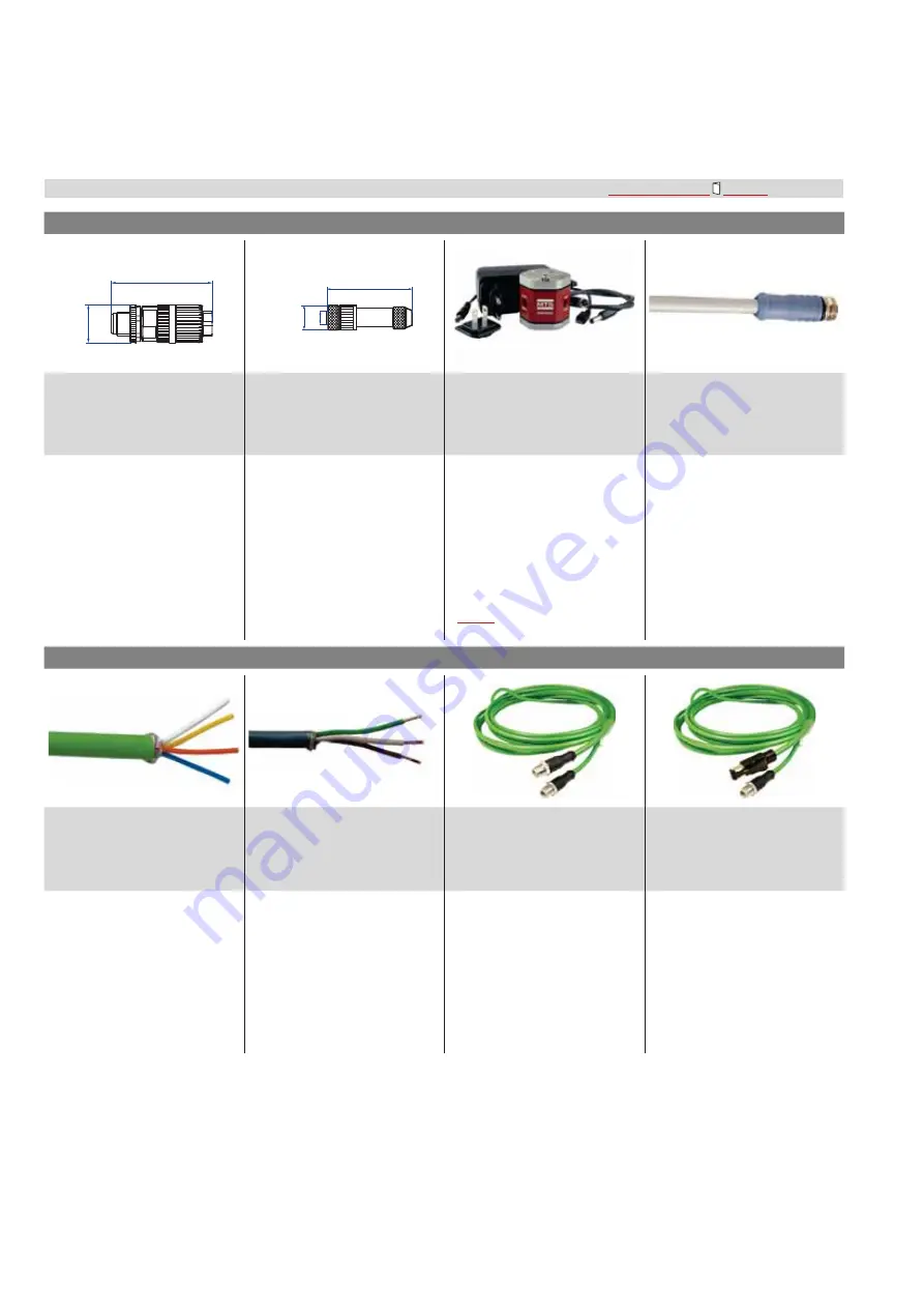
4.10 Frequently ordered accessories for POWERLINK output

 – Additional options available in our 

Accessories Guide


551 444

&DEOHFRQQHFWRUV

3URJUDPPLQJNLW

&DEOHV

52

(2.05)

Ø 19.5 

(Ø 0.77)

43

(1.7)

Ø 12

(Ø 0.47)

M8

6LJQDOFRQQHFWRU0'FRGHGPDOH
SLQVWUDLJKW
3DUWQR

3RZHUFRQQHFWRU0IHPDOH
SLQVWUDLJKW
3DUWQR

7HPSR/LQNNLWIRU7HPSRVRQLFV

®


56HULHV

V

3DUWQR7/(0IRU'

3RZHUFDEOHZLWK0IHPDOHFRQQHFWRU
SLQVWUDLJKWŋSLJWDLO
3DUWQRPIW
3DUWQRPIW
3DUWQRPIW

Material: Zinc nickel-plated
Termination: Insulation-displacement

&DEOHŸĽPPĽLQ
:LUH$:*ŋ$:*

Operating temperature:

ũĽŹ&ũĽŹ)

Ingress protection: IP65 / IP67

FRUUHFWO\ğWWHG

Fastening torque: 0.6 Nm

Material: CuZn nickel plated
Termination: Solder

&DEOHŸĽPPĽLQ

Wire: 0.25 mm2
Operating temperature:

ũĽŹ&ũĽŹ)
,QJUHVVSURWHFWLRQ,3FRUUHFWO\ğWWHG

Fastening torque: 0.5 Nm

•  Connect wirelessly via Wi-Fi enabled 

device or via USB with the diagnostic 
tool

•  Simple connectivity to the sensor 

via 24 VDC power line (permissible 
cable length: 30 m)

•  User friendly interface for mobile 

devices and desktop computers

•  See product brief “TempoLink 

smart assistant” (document part no.:


551976

) for further information

Material: PUR jacket; gray
Features: Shielded

&DEOHŸPPLQ

Operating temperature: 

ũĽŹ&ũĽŹ)

&DEOHV

385VLJQDOFDEOH
3DUWQR

39&SRZHUFDEOH
3DUWQR

6LJQDOFDEOHZLWK0'FRGHGPDOH
FRQQHFWRUSLQVWUDLJKWŋ0
'FRGHGPDOHFRQQHFWRUSLQ
VWUDLJKW
3DUWQR

6LJQDOFDEOHZLWK0'FRGHGPDOH
FRQQHFWRUSLQVWUDLJKWŋ5-
PDOHFRQQHFWRUVWUDLJKW
3DUWQR

Material: PUR jacket; green

)HDWXUHV&DWKLJKO\ĠH[LEOHKDORJHQ

free, energy chain capable, mostly oil & 

ĠDPHUHVWLVWDQW
&DEOHŸPPLQ

Cross section: 2 × 2 × 0.35 mm

2


$:*

Operating temperature:

ũĽŹ&ũĽŹ)

Material: PVC jacket; gray

)HDWXUHV6KLHOGHGĠH[LEOH
PRVWO\ĠDPHUHVWLVWDQW
&DEOHŸPPLQ

Cross section: 3 × 0.34 mm²
Bending radius: 10 × D
Operating temperature:

ũĽŹ&ũĽŹ)

Material: PUR jacket; green
Features: Cat 5e
Cable length: 5 m (16.4 ft)

&DEOHŸPPLQ

Ingress protection: IP65, IP67, IP68

FRUUHFWO\ğWWHG

Operating temperature:

ũĽŹ&ũĽŹ)

Material: PUR jacket; green
Features: Cat 5e
Cable length: 5 m (16.4 ft)

&DEOHŸPPLQ

Ingress protection M12 connector:

,3FRUUHFWO\ğWWHG

Ingress protection RJ45 connector:

,3FRUUHFWO\ğWWHG

Operating temperature:

ũĽŹ&ũĽŹ)

Follow the manufacturer‘s mounting instructions

&RQWUROOLQJGHVLJQGLPHQVLRQVDUHLQPLOOLPHWHUVDQGPHDVXUHPHQWVLQDUHLQLQFKHV

Summary of Contents for Temposonics V POWERLINK R Series

Page 1: ...Temposonics R Series V POWERLINK Operation Manual Temposonics Magnetostrictive Linear Position Sensors GENERATION V V V THE NEW ...

Page 2: ...tion 15 4 6 Replacement of sensor 16 4 7 Electrical connection 17 4 8 Frequently ordered accessories for RP5 design 18 4 9 Frequently ordered accessories for RH5 design 19 4 10 Frequently ordered accessories for POWERLINK output 20 5 Operation 21 5 1 Initial start up 21 5 2 LED status 21 5 3 Topologies and hubs 22 1RGH FRQğJXUDWLRQ RI 5 6HULHV V 32 5 1 22 6 1 Setting the node ID via TempoLink smar...

Page 3: ...nced by an external magnetic field Signal output is wrong Cables are damaged Short circuit the sensor can be destroyed sensor does not respond Spacers are missing installed in a wrong order Error in position measurement Wrong connection of ground shield Signal output is disturbed the electronics can be damaged Use of a magnet that is not specified by MTS Sensors Error in position measurement Do not ...

Page 4: ...azardous areas The sensor is not suitable for operation in explosion hazardous areas 2 See also applicable MTS Sensors terms of sales and delivery on www mtssensors com 2 5 Warranty MTS Sensors grants a warranty period for the Temposonics position sensors and supplied accessories relating to material defects and faults that occur despite correct use in accordance with the intended application2 The...

Page 5: ...20 in 1 0 in 20 100 in 2 0 in 100 200 in 4 0 in 200 250 in 10 0 in Non standard stroke lengths are available must be encoded in 5 mm 0 1 in increments e 1XPEHU RI PDJQHWV X X 01 30 position s 1 30 magnet s I RQQHFWLRQ W SH D 5 6 2 M12 female connectors 5 pin 1 M8 male connector 4 pin J 6 VWHP 1 Standard h 2XWSXW U 3 0 1 POWERLINK position and velocity 1 30 position s U 3 1 1 POWERLINK position and...

Page 6: ...in h Output is chosen select a suitable magnet 1 2 3 4 5 6 7 8 9 10 11 12 13 14 15 16 17 18 19 20 5 H 5 D 5 6 1 U 3 1 D b c d e I J h D 6HQVRU PRGHO 5 H 5 Rod b HVLJQ B Base unit only for replacement J 7KUHDGHG Ġ DQJH 0 ū J URG PP stroke length 25 5900 mm 1 232 in M 7KUHDGHG Ġ DQJH 0 ū J VWDQGDUG 6 7KUHDGHG Ġ DQJH ŧ 81 VWDQGDUG T 7KUHDGHG Ġ DQJH ŧ 81 ZLWK UDLVHG IDFH c 0HFKDQLFDO RSWLRQV A Standar...

Page 7: ...delivery RP5 profile sensor Sensor Position magnet not valid for RP5 with design O 2 mounting clamps up to 1250 mm 50 in stroke length 1 mounting clamp for each 500 mm 20 in additional stroke length RH5 rod sensor RH5 B Base unit without flange rod assembly 3 socket screws M4 RH5 J M S T Sensor O ring MAC 00 03 CA 00 58 F6 S N 19020950 12JAN2019 RH5SA0080M01D561U301 Order code MAC address Date of Pr...

Page 8: ...ide The momentary interaction of the magnetic fields releases a torsional strain pulse that propagates the length of the waveguide When the ultrasonic wave reaches the end of the waveguide it is converted into an electrical signal Since the speed of the ultrasonic wave in the waveguide is precisely known the time required to receive the return signal can be converted into a linear position measurem...

Page 9: ... is firmly installed and the position magnet is fastened to the mobile machine part Thus it can travel along the sensor profile The sensor is fitted on a flat machine surface using the mounting clamps Fig 4 A length dependent number of these clamps are delivered with the sensor and must be distributed over the profile at regular distances For fastening use M5 20 screws to DIN 6912 that should be tighte...

Page 10: ...b A F 46 53 2 09 A F 44 5 1 75 51 3 2 02 a b RH5 T A V RH5 with threaded raised face flange 16 UNF 3A 17 0 67 Ø 25 4 Ø 1 Threaded flange T 16 UNF 3A Stroke length 25 7620 1 300 Sensor electronics housing 65 5 2 58 Null zone 51 2 01 Magnet Stroke length 5000 mm 196 9 in Dead zone 63 5 66 2 5 2 6 Ø 10 0 13 Ø 0 39 0 01 2 5 0 1 25 0 98 51 3 2 02 A F 44 5 A F 1 75 Mechanical option B Bushing on rod end f...

Page 11: ...nge J M22 1 5 6g Magnet Ø 12 7 0 13 Ø 0 5 0 01 Dead zone 73 6 2 9 25 0 98 RH5 B A V RH5 base unit only for replacement 48 1 89 17 0 67 Sensor electronics housing 58 2 28 Null zone 61 2 4 Stroke length 25 7620 1 300 Dead zone 52 54 57 2 05 2 13 2 24 Stroke length 25 1575 1 62 52 2 05 dead zone Stroke length 1576 5000 62 05 196 9 54 2 13 dead zone Stroke length 5001 7620 196 9 300 57 2 24 dead zone ...

Page 12: ... 1 5 6g or M22 1 5 6g provide a screw hole based on ISO 6149 1 Fig 11 See ISO 6149 1 for further information Sealing via O ring in the flange undercut Sealing via O ring in cylinder end cap groove Raised face Sealing via O ring in the flange undercut 1 2 a 2 b Note the fastening torque RH5 M 65 Nm RH5 S 50 Nm RH5 T 55 Nm RH5 J 125 Nm Seat the flange contact surface completely on the cylinder mounting...

Page 13: ...gnetic material is used observe the specified dimensions Fig 15 Magnet mounting with magnetic material When using magnetic material the dimensions of Fig 15 must be observed A If the position magnet aligns with the drilled piston rod B If the position magnet is set further into the drilled piston rod install another non magnetic spacer e g part no 400 633 above the magnet Fig 13 Mounting of U magne...

Page 14: ...of mounting Sensor electronics housing Stroke length 5000 mm 196 9 in End position 68 5 73 5 2 7 2 9 Start position 25 5 1 RH5 with ring magnet U magnet Sensor electronics housing Reference edge of mounting Start position 51 2 01 End position 63 5 66 2 5 2 6 Stroke length 5000 mm 196 9 in RH5 with block magnet Sensor electronics housing Reference edge of mounting Start position 48 5 1 91 End posit...

Page 15: ...he marking on the magnet points to the same direction as the elongated status LED in the lid of the sensor electronics housing NOTICE The generated linearization might deviate from the linearity tolerances re garding different environmental conditions In addition the use of a dif ferent position magnet or more position magnets may cause differences Fig 19 Magnet alignment of ring magnet for RH5 PO...

Page 16: ... Fig 24 for the sensor designs M S and T The sensor can be replaced without interrupting the hydraulic circuit 3 Insert the new base unit Mount the ground lug on a screw Tighten the screws Fastening torque 1 4 Nm Fig 23 Replacement of the base unit e g RH5 sensor part 2 NOTICE When replacing the base unit make sure that no humidity enters the sensor tube This may damage the sensor Secure the base ...

Page 17: ...etween machine and electronics earth connections no compensating currents are allowed to flow across the cable shielding Recommendation Install potential compensating leads with large cross section or use cables with separate double shielding and connect only one end of the shield Use only stabilized power supplies in compliance with the specified electrical ratings Grounding of profile and rod senso...

Page 18: ...UR J Operating temperature ũ Ľ Ź ũ Ľ Ź 3RVLWLRQ PDJQHWV 0RXQWLQJ DFFHVVRULHV Ø 32 8 Ø 1 29 Ø 23 8 Ø 0 94 Ø 13 5 Ø 0 53 Ø 4 3 Ø 0 17 60 140 3 0 12 7 9 0 31 19 5 0 77 1 5 0 06 33 1 3 14 0 55 20 5 0 81 14 9 0 59 8 2 0 31 0 08 Distance to sensor element Ø 4 3 Ø 0 17 4 holes Ø 5 3 Ø 0 21 28 1 1 9 0 35 50 1 97 2 0 08 68 2 68 9 5 0 37 Mounting clamp width 14 6 0 57 4 0 16 11 5 0 45 4 5 1 8 8 0 31 M5 thre...

Page 19: ...0 77 1 5 0 06 33 1 3 14 0 55 20 5 0 81 14 9 0 59 8 2 0 31 0 08 Distance to sensor element Ø 4 3 Ø 0 17 Ø 14 3 Ø 0 56 Ø 23 8 Ø 0 94 Ø 31 8 Ø 1 25 Ø 4 3 Ø 0 17 3 2 0 13 Ø 15 3 Ø 0 6 Ø 2 2 Ø 0 09 Ø 16 4 Ø 0 65 Ø 2 2 Ø 0 09 ORFN PDJQHW 3DUW QR 0DJQHW VSDFHU 3DUW QR 2 ULQJ IRU WKUHDGHG Ġ DQJH 0 ū J 3DUW QR 2 ULQJ IRU WKUHDGHG Ġ DQJH ŧ 81 3DUW QR Material Plastic carrier with hard ferrite magnet HLJKW S...

Page 20: ...computers See product brief TempoLink smart assistant document part no 551976 for further information Material PUR jacket gray Features Shielded DEOH PP LQ Operating temperature ũ Ľ Ź ũ Ľ Ź DEOHV 385 VLJQDO FDEOH 3DUW QR 39 SRZHU FDEOH 3DUW QR 6LJQDO FDEOH ZLWK 0 FRGHG PDOH FRQQHFWRU SLQ VWUDLJKW ŋ 0 FRGHG PDOH FRQQHFWRU SLQ VWUDLJKW 3DUW QR 6LJQDO FDEOH ZLWK 0 FRGHG PDOH FRQQHFWRU SLQ VWUDLJKW ŋ ...

Page 21: ...ion to the next network node established Flashing OFF Connection to the next network node established communication active 3RUW MS ER NS RN UHHQ 5HG QIRUPDWLRQ ON OFF Connection to the next network node established Flashing OFF Connection to the next network node established communication active 5 2 LED status A diagnostic display on the lid of the sensor informs about the current status of the se...

Page 22: ...n of TempoLink smart assistant to sensor and power supply Before changing the node ID at the sensor and connecting TempoLink smart assistant to the sensor disconnect the sensor from the power supply and if the sensor is connected to a control disconnect it too Use the adapter cable for connection of the TempoLink smart assistant to the R Series V sensor Connect the barrel connector of the adapter ...

Page 23: ...us of the connection between the TempoLink smart assistant and the sensor 3 The integrated Wi Fi access point does not provide internet access Fig 34 Connection status RQQHFWLRQ VWDWXV UHHQ QIRUPDWLRQ ON Connection to sensor is established 5HG QIRUPDWLRQ ON Connection to sensor is not established OXH QIRUPDWLRQ ON Sensor in command mode NOTICE Only one device can be connected to the TempoLink smar...

Page 24: ...ction icon changes to green 6 1 4 Graphical User Interface GUI Click the menu symbol in the top left to get to the main menu Fig 35 Main menu of the graphical user interface GUI Fig 36 Starting the command mode to change settings of the connected sensor After entering the command mode the connection icon on the top right will turn from green to blue A pencil icon will appear to the right of the no...

Page 25: ...ed In this example the node ID of the first controlled node found with vendor ID 0x40 is set to 1 STATE_RESET_NODE PLC enters into this state when the operations of STATE_SET_NODE_ID have been finished The sensor has to be reset in order to communicate using the new node ID In this state a reset of the sensor is done STATE_CHECK_NODE_ID PLC enters into this state when the operations of STATE_RESET_N...

Page 26: ...5 Program executed by PLC cyclically SdoAccessCyclic c This program implements the state machine and changes the node ID of R Series POWERLINK as well as R Series V POWERLINK source code on page 27 Source Code SdoAccessInit c COPYRIGHT Program SdoAccess File SdoAccessInit c Author SSchumacher Created November 18 2014 Implementation of program SdoAccess include bur plctypes h ifdef _DEFAULT_INCLUDE...

Page 27: ...doWrite pData u8NodeIdToSet variable containing value to set fbSdoWrite datalen sizeof u8NodeIdToSet size of the variable containing value to set fbSdoWrite enable 1 enable write operation fbSdoRead enable 0 disable read operation go to next step iState break case STATE_RESET_NODE fbSdoWrite pDevice SS1 IF1 interface sensor is connected to fbSdoWrite node u8NodeFoundAt node id of sensor fbSdoWrite...

Page 28: ... As shown in the screenshot of the variable watch a controlled node with vendor ID from MTS Sensors has been found at node ID 32 The node ID has been successfully set to 1 Fig 44 Variable watch Fig 45 I O mapping of sensor with changed node ID As shown in the screenshot of the I O mapping the sensor is working well using its new node ID ...

Page 29: ...and functions of the device such as timing and configurable device parameters The XDD file enables simple and easy integration of a POWERLINK device into a project engineering tool The XDD file for R Series V POWERLINK is packed in a zip file which is available for download on our homepage www mtssensors com LJ 6WDUWLQJ WKH UG 3DUW HYLFH 0DQDJHU In the opening window the already imported 3rd Party Dev...

Page 30: ...D previously set on the sensor must be set on the controller Click on the sensor in the physical view with the right mouse button and select the entry Node Number Æ Change Node Number Fig 52 The node number on the control must be identical to the node ID of the device The default node ID of R Series V POWERLINK is 1 See the sections 6 1 and 6 2 to change the node ID of R Series V POWERLINK LJ 6HOH...

Page 31: ...he sensor that can be transferred cyclically To activate cyclic transmission of a specific data item click on the data item column called Value and change the entry from None to Read Fig 54 Device specific parameters Configuration parameters of the sensor which are transferred in the startup phase LJ FWLYDWLQJ WKH PDSSLQJ RI WKH SDUDPHWHUV RI WKH JURXS Ń KDQQHOVń ...

Page 32: ...QHV WKH VWDWXV ELW RI WKH 0 LQ D 0 FKDQQHO IRU XS WR PDJQHWV ō LW YDOXH 0 LQDFWLYH ō LW YDOXH 0 DFWLYH 0 Number of entries Variable ro Unsigned8 1 30 0 VWDWH UHJLVWHU IRU PDJQHWV Ľ Variable ro Unsigned8 6400 UHD VWDWH UHJLVWHU UUD This object contains the actual area status of the encoder position for up to 30 magnets If the position is out of range a bit will be set in the related position line 0...

Page 33: ...PV 2 Status data version Variable ro Integer32 Version number 3 Operational time Variable ro Integer32 Total operational time of the sensor 4 Odometer Variable ro Integer32 Total distance travelled by the position magnet 5 Magnet cycles Variable ro Integer32 Total number of directional changes of the magnet 6 Minimum input voltage Variable ro Integer32 Minimum input voltage so far 7 Maximum input ...

Page 34: ...Variable ro Unsigned8 1 30 0 ORZ OLPLW IRU Ľ PDJQHWV Variable rw Integer32 6320 CAM 1 high limit Array This object determines the upper limit of position for 0 1 It can be set for up to 30 magnets 0 Number of entries Variable ro Unsigned8 1 30 0 KLJK OLPLW IRU Ľ PDJQHWV Variable rw Integer32 6321 CAM 2 high limit Array This object determines the upper limit of position for 0 2 It can be set for up...

Page 35: ...000 0 1 RPLVVLRQLQJ GLDJQRVWLF FRQWURO 0 Disabled 1 Enabled This parameter must be enabled to send out alarms object 6503 2 6FDOLQJ IXQFWLRQ 0 Disabled 1 Enabled This parameter is used to change the position resolution of the encoder 3 0HDVXULQJ GLUHFWLRQ 0 Forward 1 Reverse Setting the measuring direction 12 6 QFKURQL DWLRQ PRGH 0 Disabled 1 Enabled Setting the synchronization of the sensor to th...

Page 36: ...y explicitly authorized by MTS Sensors For return see section 2 6 Return on page 4 8 4 List of spare parts No spare parts are available for this sensor 8 5 Transport and storage The conditions of transport and storage of the sensor match the operating conditions mentioned in this document 8 Maintenance and troubleshooting 9 Removal from service dismantling The product contains electronic component...

Page 37: ...dity no condensation Ingress protection 3 FRQQHFWRUV FRUUHFWO ğWWHG Shock test 150 g 11 ms IEC standard 60068 2 27 Vibration test 30 g 10 2000 Hz IEC standard 60068 2 6 excluding resonant frequencies EMC test Electromagnetic emission according to EN 61000 6 3 Electromagnetic immunity according to EN 61000 6 2 The sensor meets the requirements of the EC directives and is marked with Magnet movement...

Page 38: ... 60068 2 6 excluding resonant frequencies RH5 J 15 g 10 2000 Hz IEC standard 60068 2 6 excluding resonant frequencies EMC test Electromagnetic emission according to EN 61000 6 3 Electromagnetic immunity according to EN 61000 6 2 The sensor meets the requirements of the EC directives and is marked with Operating pressure 350 bar 5076 psi 700 bar 10 153 psi peak at 10 1 min for sensor rod RH5 J 800 ...

Page 39: ... 3001 Sheldon Drive DU 1 86 Tel 1 919 677 0100 Fax 1 919 677 0200 info us mtssensors com www mtssensors com Safety Declaration Dear Customer If you return one or several sensors for checking or repair we need you to sign a safety declaration The purpose of this declaration is to ensure that the returned items do not contain residues of harmful substances and or that people handling these items wil...

Page 40: ... Notes 3 And 4 32 in 32 in 125 in B 1 105 in Minimum Full Thread Depth 0 875 in dia 0 015 0 000 0 769 in dia 0 015 0 000 0 500 in dia 0 005 in dia FIM A 45 5 15 1 0 094 in max 0 008 in 0 004 in 0 125 in 0 125 in 3 4 16 UNF 2B Thread R 0 813 in dia 0 002 in 0 106 in 0 008 in A 0 008 A 0 004 A R0 015 in max Pitch dia 1 180 in Recommended Minimum Spotface Diameter See Note 1 0 866 in dia Minimum See ...

Page 41: ...rization offers an improved linearity for an overall higher accuracy of the position measurement The internal lineariza tion is set for the sensor during production M 0DQDJLQJ 1RGH 01 The Managing Node usually an industrial PC or a PLC controls the communication in the network as master and sets the clock for the synchronization of all devices In a network there is only one 0DQDJLQJ 1RGH OO RWKHU ...

Page 42: ...ement for motion controlled applications V 9HQGRU XQLTXH LGHQWLğ FDWLRQ QXPEHU DVVLJQHG WR HDFK SLHFH RI computer hardware X ğ OH The properties and functions of a POWERLINK device are described LQ D ğ OH XML Device DHVFULSWLRQ 7KH 0 EDVHG ğ OH contains all relevant data that are important for the implementation of the device in the controller as well as for data exchange during RSHUDWLRQ 7KH ğ OH...

Page 43: ...s com JAPAN UDQFK 2Iğ FH Phone 81 3 6416 1063 E mail info jp mtssensors com www mtssensors com MTS Temposonics and Level Plus are registered trademarks of MTS Systems Corporation in the United States MTS SENSORS and the MTS SENSORS logo are trademarks of MTS Systems Corporation within the United States These trademarks may be protected in other countries All other trademarks are the property of th...

Reviews: