MTS Sensors TempoLink Smart Assistant Operation Manual Download Page 9

TempoLink Smart Assistant

Operation Manual

I

 9 

I

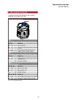
Fig. 10: LED connection status

9.  LEDs of TempoLink smart assistant

Three LEDs in the lid of the TempoLink smart assistant 

display the current status of the tool:

TempoLink smart assistant LEDs

Status LEDs

LED A
Communication between TempoLink sensor assistant and sensor

LED color

Information

Green

ON

Sensor connected

Red

ON

Data transfer from TempoLink sensor assistant 

to sensor

Orange

ON

Sensor connected and data transfer from 

TempoLink sensor assistant to sensor

LED B
Communication between sensor and TempoLink sensor assistant

LED color

Information

Red

ON

TempoLink sensor assistant receives data from 

connected sensor

OFF

No sensor connected

LED C 
USB & Wi-Fi connection

LED color (up)

Information

Green

ON

USB connection exists

Red

ON

USB connection error

OFF

No USB connection

LED color (down)

Information

Green

ON

Wi-Fi activated on TempoLink sensor assistant

Red

ON

Wi-Fi error on TempoLink sensor assistant

Summary of Contents for TempoLink Smart Assistant

Page 1: ...TempoLink Smart Assistant Operation Manual Temposonics Magnetostrictive Linear Position Sensors GENERATION I AM V THE NEW...

Page 2: ...R Series V sensor 6 5 Connection of TempoLink smart assistant to power supply 7 5 1 Using the plug in power supply with plug adapters 7 5 2 Using the cable for insertion in an existing sensor power s...

Page 3: ...to the described product or connected devices In this documentation safety information and warnings to avoid danger that might affect the life and health of operating or service personnel or cause mat...

Page 4: ...ation electron ics e g a PLC IPC indicator or other electronic control unit 2 TempoLink smart assistant is an accessory for Temposonics R Series V sensors for reading out and adjusting of sensor param...

Page 5: ...sor and TempoLink smart assistant regularly and provide documentation of the checks 7 Before system switch on ensure that nobody s safety is jeopardized by starting machines 2 4 Safety instructions fo...

Page 6: ...r power supply disconnect the power supply before connecting TempoLink smart assistant to the sensor TempoLink smart assistant Plug in power supply with plug adapters or cable for insertion in an exis...

Page 7: ...xxx indicates the last four digits of the serial number OUTPUT INPUT SENS OR 24V DC OUTPUT INPUT SENS OR 24V DC 5 2 Using the cable for insertion in an existing sensor power supply with sensor mating...

Page 8: ...l hours of the sensor Odometer total distance travelled by the position magnet Magnet cycles total number of directional changes of the magnet Sensor Info includes information about the connected sens...

Page 9: ...nsfer from TempoLink sensor assistant to sensor Orange ON Sensor connected and data transfer from TempoLink sensor assistant to sensor LED B Communication between sensor and TempoLink sensor assistant...

Page 10: ...TempoLink Smart Assistant Operation Manual I 10 I Notes...

Page 11: ...TempoLink Smart Assistant Operation Manual I 11 I Notes...

Page 12: ...p mtssensors com www mtssensors com MTS Temposonics and Level Plus are registered trademarks of MTS Systems Corporation in the United States MTS SENSORS and the MTS SENSORS logo are trademarks of MTS...

Reviews: