


TempoLink Smart Assistant
Operation Manual
I
8
I
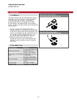
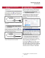
After the connection via Wi-Fi or USB is established, open the
browser and go to the website-URL:
http ://tempolink/
The green or red circle in the top right shows the status of
the connection between the TempoLink smart assistant and
the sensor.
Fig. 7: Start page of the graphical user interface
Fig. 8: Connection status
Connection status
Green
Information
ON
Connection to sensor is established
Red
Information
ON
Connection to sensor is not established
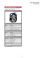
Click the menu symbol in the top left to get to the main
menu:
TempoLink:
includes information about the TempoLink smart
assistant like its serial number, firmware version and product
number. In addition the password for the Wi-Fi access point
can be changed.
Status:
includes current information about the sensor status
like
• Position of the magnet(s)
• Temperature inside sensor electronic housing
• Input voltage
• Operational time: total operational hours of the sensor
• Odometer: total distance travelled by the position magnet
• Magnet cycles: total number of directional changes of the
magnet
Sensor Info:
includes information about the connected
sensor like stroke length, serial number and order code.
The displayed information depends on the sensor protocol.
Parameters:
includes information about the operational
settings of the connected sensor. The displayed parameters
depend on the sensor protocol and some operational settings
may not be adjustable.
Network:
includes information about the network settings of
the connected sensor. The displayed information depends on
the sensor protocol.
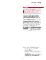
NOTICE
Only one device can be connected to the TempoLink smart
assistant at a time in order to display the graphical user
interface.
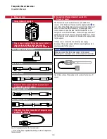
NOTICE
Disable all Wi-Fi and LAN connections before connecting
TempoLink smart assistant via USB.
Connecting to the user interface may take longer if Wi-Fi
and LAN connections are active.
USB connector
Fig. 6: USB port on the TempoLink smart assistant
7. Establishing a connection via browser
8. Graphical user interface
Fig. 9: Main menu of the graphical user interface