background image


Section Six: Instrument Measurement 


Warning


During  the  operation,  never  apply  more  than  30V 

between any two terminals, or between any terminal and 
earth ground. Any voltage more than 30V will not only do 
damage  to  the  Instrument,  but  also  lead  to  possible 
personal injury.  


Caution


During the operation, do not apply a voltage or current 

exceeding  the  measuring  range  to  the  input  terminal, 
which will cause possible damage to the Instrument. 

• When  connecting  to  the  Instrument,  the  power  supply 

of the device under test should be cut off. Otherwise, 
any  connection  with  a  device  without  cutting  off  its 
power  supply  will  cause  possible  damage  to  the 
Instrument. 


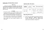
Input Operation Procedure 


Function 

Operation 

Operation 

Display 

Measurement Range 

DCI    20 mA 


DCV    28 V  


20 mA 


00.000  mA 


-25.00 mA 


0.000  V 


-1.000

22.000 mA 


-31.25

112.50 mA % 


-0.2000

28.000 V 


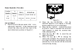
Measuring DC Current 
 

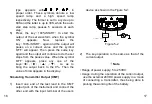
1)  Insert one end of the test lead into the mA jack 

of  the  Instrument 

INPUT

terminal  and 

connect  the  other  end  to  the  output  of  the 
user’s device as shown in Figure 5-3: 


18 

19 

Summary of Contents for 7205

Page 1: ... and defects resulting from action of the user such as misuse improper wiring operation outside of specification improper maintenance or repair or unauthorized modification MTP Instruments specifically disclaims any implied warranties or merchantability or fitness for a specific purpose and will not be held liable for any direct indirect incidental or consequential damages MTP Instruments total li...

Page 2: ...ationinstruction Warning A warning shows that if the operation does not comply with the following correct instruction it is possible to bring hazards to the user or cause damage to the instrument in use The warning also points out how to avoidtheaccidents Caution A caution shows that if the operation does not comply with the following correct instruction it is possible to cause damage to the instr...

Page 3: ...e of the Instrumentexceptprofessionals Periodically wipe the case with a damp cloth and detergent donotuseanycorrosivesolvents Note To keep the Instrument in a designed accuracy it needs warmingup5minutesbeforeitisputintooperation If any user requires a higher accuracy of the calibrator he orshe isrequested tomakecontact withthemanufactureror ourproductdistributors Section Two Instrument Panel Lay...

Page 4: ...ate of calibration 0 FS When the symbol O or FS appears during the calibration it denotes that the zero point or the full scale point is being calibrated When this symbol appears it denotes that the battery is nearly used up and needs replacing When this symbol appears it denotes that the output digits need setting V mA These symbols denote the units of both present input and output values ON OFF ...

Page 5: ...test leads 2 Shake out any dirt that may be in terminals 3 Soak a new swab with alcohol Clean each terminal with the swab Replacing the Batteries This Instrument is powered by two AA batteries IEC LR6 Warning To avoid electrical shock or personal injury Remove Test Leads from the Instrument before opening the battery door Close and latch the Battery Cover before using the meter Note The new and ol...

Page 6: ...eries Replacing Fuse Warning To avoid personnel injury or damage to the meter use only the specified fuse The specification is 63mA 250V fast melt Replace the fuse as follows Refer to Figure 3 2 if necessary 1 Remove the test leads from the meter and turn the meter OFF 2 Take off the protector of the meter remove the four screws by using a standard blade screwdriver and then take off the cover 3 R...

Page 7: ...ff the power pausing 5 seconds and then restart the Instrument Automatic Power off The factory default setting is that the Instrument will cut off the power automatically if no operation applied to the Instrument within 15 minutes Users can decide whether they want to use this function or not See Section 7 for reference Section Five Output from Instrument The Instrument produces the DC current fro...

Page 8: ...0 V IN P U T O U T P U T C O M m A V L O O P X M T m A Figure 5 1 2 Press the key OUTPUT IN and the OUTPUT appears in the display It denotes that the Instrument is in an output state 3 Press the key mA V to select the output to be set in mA or and then the unit mA or mA appears in which 0 denotes 4mA 100 denotes 20mA 4 Press the key to select the set digits of the output 5 Press the key to change ...

Page 9: ...y is pressed the OUTPUT appears in the LCD it denotes the Instrument is in an output state 3 Press the key 100 START and the symbols 0 FS will appear in the display 4 Press the key to be set to 100 and the current output will be 20mA Press the key to be set to 0 and the current output will be 4mA 5 Repress the key 100 START so as to exit the step current output Auto ramp Output 1 Connect as shown ...

Page 10: ...mbol OFF appears press any one of the keys so as to bring the output back to the 0 Then the value of 4mA appears in the display Simulating Transmitter Output XMT 1 Insert one end of the test lead to the XMT output jack of the Instrument and connect the other end with the input terminal of the user s device as shown in the Figure 5 2 M A X 3 0 V 3 0 V M A X M A X 3 0 V IN P U T O U T P U T C O M m ...

Page 11: ...age to the Instrument When connecting to the Instrument the power supply of the device under test should be cut off Otherwise any connection with a device without cutting off its power supply will cause possible damage to the Instrument Input Operation Procedure Function Operation Operation Display Measurement Range DCI 20 mA DCV 28 V 20 mA 00 000 mA 25 00 mA 0 000 V 1 000 22 000 mA 31 25 112 50 m...

Page 12: ...L if the measured value exceeds the measuring range Measuring DC Voltage 1 Insert one end of the test lead into the V jack of the Instrument INPUT terminal and connect the other end to the output of the user s device as shown in Figure 5 4 2 Press the key OUTPUT IN the LCD displays INPUT and it denotes that the Instrument is in an input state 3 Press the key mA V to select V function and the LCD d...

Page 13: ...llowing operation will change the auto power off function of the Instrument In power off state press the keys mA V and power simultaneously to power on and release the mA V key only after the LCD displays all the contents The Instrument enters into the calibration mode and the symbols AP XX appear in the LCD Press the key and when the LCD displays AP OF the Instrument removes auto power off functi...

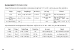
Page 14: ...1mA 0 05 set value 4uA Max load 1KΩat 20mA Note power supply range 5 25VDC Loop Power Supply 24V 10 Max output current up to 25mA Input Performance Index applicable to temperature range from 18 to 28 within one year after calibration Input Range Output Range Resolution Accuracy Remark Voltage 28V 0 200 28 000V 1mV 0 02 reading 2mV Input resistance about 1MΩ Current 20mA 1 000 22 000mA 0 001mA 0 02...

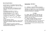
Page 15: ...ty Certified as compliant to IEC1010 provisions Safety standard issued by International Electrotechnical Commission Section Nine Calibration Note Calibration In order to keep the designed accuracy of this Instrument it is recommendable to calibrate your calibrator once a year The following example shows the use of recommended standard equipment to perform the calibration Caution Usage Never apply ...

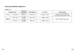
Page 16: ...t Output Range Accuracy Recommended Output DCA 20mA Digit meter MAX 22 mA 50ppm 0 4uA Digit meter KEITHLEY 2000 Standard resistance BZ10 100Ω Measure ment DCA 20mA Standard source MAX 33mA 100ppm 0 2uA 5520 FLUKE or equivalent DCV 28V Standard source MAX 33V 12ppm 15uV 28 29 ...

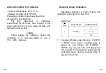
Page 17: ...ply for calibrator during the calibration it is recommendable to use 2 1 5V LR6 batteries Operating Output Calibration Operating calibration in order of items and calibration points listed in Table 10 2 Table 10 2 Item No Output Range Calibration Point 1 DCA 20mA 0 0 FS FS 1 In power off state press the keys OUTPUT INPUT and power simultaneously to power on and release the OUTPUT INPUT key only af...

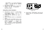
Page 18: ...tor to a value in identity with the reading of the digit meter 6 Press the key 100 START and the LCD displays SAVE denoting that the calibrated point has been stored L O B Z 1 0 H I K E IT H L E Y 2 0 0 0 Figure 10 1 7 Press the key STEP AUTO and the LCD displays CAL 0 FS With the output stabilized repeat the operation of steps 5 and 6 8 Press the key STEP AUTO and the LCD displays CAL 0 FS With t...

Page 19: ... OUTPUT INPUT key only after the LCD displays all the contents The Instrument enters into the calibration mode and the symbols CAL 0 appear in the LCD 2 Press the OUTPUT INPUT key to select measurement function and the LCD displays INPUT mA 3 Connect to the Instrument as shown in Figure 10 2 T R IG O U T A U X S C O P E L o N O R M A L H i S ta n d a rd S o u rc e 5 5 2 0 A Figure 10 2 4 Set the s...

Page 20: ...CAL 0 V 2 Connect to the Instrument as shown in Figure 10 3 3 Set the standard source to an appropriate range 4 Set the output of standard source as the value given in Table 10 3 and when the output stabilized press the key 100 START and the LCD displays SAVE denoting that the calibrated point has been stored T R IG O U T A U X S C O P E L o N O R M A L H i S ta n d a rd S o u rc e 5 5 2 0 A Figur...

Page 21: ...present manufacturer is not liable for any accident and hazard arising from the customer misuse or inadvertent operation The functions described in this operation instruction should not be used as grounds to apply this product to a particular purpose Les Instruments MTP Instruments Head Office 4409 Charleroi street Montreal North Quebec H1H 1T6 Telephone 514 326 7167 Fax 514 326 7838 Toll Free Num...

Reviews: