


7
Tractor Model Series 600 & 610
Mounting Bracket Assembly
NOTE:
For convenience, pivot the seat forward and
leave it in that position until the grass collector is fully
mounted and assembled.
•
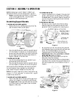
Remove the hairpin clip and clevis pin from the rear
of the mounting bracket assembly.
•
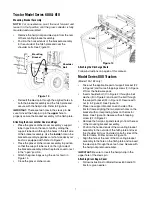
Position the hooked ends of the bracket assembly
to the outside of the hitch plate and over the
shoulder bolts. See Figure 13.
Figure 13
•
Reinsert the clevis pin through the aligned holes in
both the bracket assembly and the hitch plate and
secure with the hairpin clip. Refer to Figure 6.
IMPORTANT:
There are two holes in the clevis pin. Be
sure to insert the hairpin clip in the
upper
hole to
properly secure the bracket assembly to the hitch plate.
Attaching the Grass catcher Cover and Bags
•
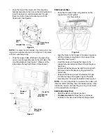
Place the grass catcher cover assembly’s support
tube in position on the rear of unit by sliding the
support tube down through the holes in the left side
of the bracket assembly. Use the
inside
hole on the
bracket assembly regardless of what size deck your
tractor is equipped with. Refer to Figure 7.
•
Place the grass catcher cover assembly in position
so that the support tube rests on the right side of
the bracket assembly. Allow the plastic cover to rest
in the “open” position.
•
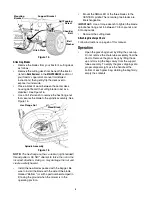
Attach the grass bags using the slots shown in
Figure 14.
•
Close the grass catcher cover.
Figure 14
Attaching the Discharge Chute
Follow instructions on page 5 of this manual.
Model Series 800 Tractors
(Model 190-182 only)
•
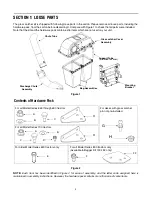
Take out the applicable pair of support bracket (F2
in Figure 2)and four self-tapping screws (F in Figure
2) from the hardware pack.
•
Insert shoulder bolt (C in Figure 2) through a bell
washer (B in Figure 2) and insert the bolt through
the support bracket (F2 in Figure 2). Secure with
nut (A in Figure 2). See Figure 15.
•
Place one support bracket on each side of the
tractor frame aligning the two smaller holes on the
bracket with corresponding holes on the tractor
frame. See Figure 15. Secure with self-tapping
screw (FF in Figure 2).
•
Remove the hairpin clip and clevis pin from the rear
of the mounting bracket assembly.
•
Position the hooked ends of the mounting bracket
assembly to the outside of the hitch plate and over
the shoulder bolts just installed on both sides of the
tractor frame. Follow arrows in Figure 15.
•
Align the hole at the rear of the mounting bracket
assembly to the hole on the hitch plate and re-insert
the clevis pin through these two holes. Secure with
the hairpin clip removed earlier.
IMPORTANT:
Be sure to insert the hairpin clip in the
upper hole of the clevis pin.
Attaching Grass Bag & Cover
•
Follow instructions for Model Series 600 and 610
tractors, given earlier.
Mounting
Bracket
Shoulder
Bolt
Slots
Slots
Summary of Contents for OEM-190-180
Page 9: ...9 NOTES ...


